
Control Line: Aerobatics
Ted Fancher
Introduction
Last month's discussion was devoted to the "lowly" control handle and to a strictly mechanical examination of control response rate. It did not necessarily represent what we feel at the handle. To better understand how much work we have to put into flying that beast, we have to check out the handle's overhang and its effects on "control feel."
Definition of overhang
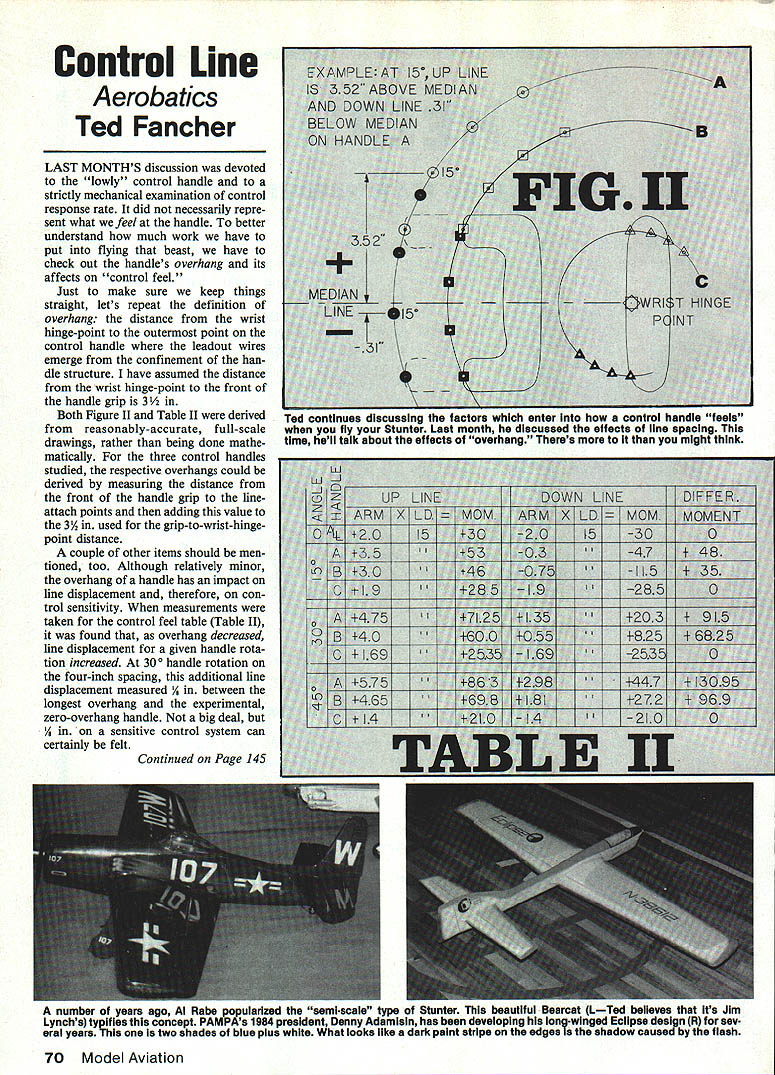
Just to make sure we keep things straight, here's the definition of overhang: the distance from the wrist hinge-point to the outermost point on the control handle where the leadout wires emerge from the confinement of the handle structure. I have assumed the distance from the wrist hinge-point to the front of the handle grip is 3½ in.
Both Figure II and Table II were derived from reasonably accurate, full-scale drawings rather than being done mathematically. For the three control handles studied, the respective overhangs could be derived by measuring the distance from the front of the handle grip to the line-attach points and then adding this value to the 3½ in. used for the grip-to-wrist-hinge-point distance.
A couple of other items should be mentioned. Although relatively minor, the overhang of a handle has an impact on line displacement and, therefore, on control sensitivity. When measurements were taken for the control-feel table (Table II), it was found that, as overhang decreased, line displacement for a given handle rotation increased. At 30° handle rotation on the four-inch spacing, this additional line displacement measured ¾ in. between the longest overhang and the experimental, zero-overhang handle. Not a big deal, but ¾ in. on a sensitive control system can certainly be felt.
How overhang affects control feel
To understand the effect of overhang on control feel, it is necessary to understand that the feel in our handle is made up of inputs from both the Up and Down lines. The input of each line is made up of two elements: the actual tension (arbitrarily stated here as 15 lb per line) and the vertical distance from the point at which the tension force is applied to the wrist hinge-point. We will measure the tension in pounds and the distance components in inches, with the resulting moment expressed in inch-pounds.
Take a look at Figure II. You will notice the horizontal line running from the wrist hinge-point horizontally through the center of the handle with a large Plus above and a large Minus below. This is the median line from which the distance measurement will be taken. Any line-attach point falling above this line will be considered a positive value and thus a force to be overcome in "up" maneuvers. Any line-attach point below this line will be considered a negative value and thus an assisting force in "up" maneuvers.
To determine the moment of each line, multiply the tension (lb) by the perpendicular distance (in) to the median line. The algebraic sum of the two moments gives the net moment about the wrist hinge-point. Points below the median line are considered negative and thus a force helping to overcome the Up-line load. Please note that it is entirely possible, indeed quite normal, for both line-attach points to be above the median line and thus both apply positive values which are added together to get total differential feel.
Remember that we are only discussing "up" maneuvers here; the reverse of our findings will be true for "down."
Measurements and handles studied
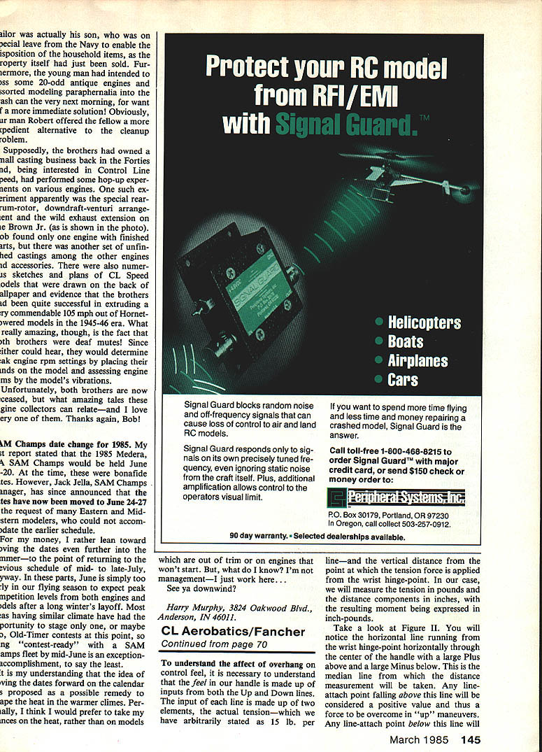
Measurements were taken from Figure II at 0°, 15°, 30°, and 45° of rotation for each of three handles, all with four-inch line spacing:
- A: a Hot Rock with 1½-in. overhang extensions
- B: a stock Hot Rock
- C: a handle with the attach points directly above and below the wrist hinge-point (informational only; not recommended)
The measurements taken were entered into Table II, the simple math done, and the resulting differential moment (or "feel") deduced for each parameter.
Worked examples
All the handles at 0° of rotation (neutral) show the following. All Up lines are 2 in. above the median line and carry 15 lb loads: plus 2 in. × 15 lb = plus 30 in.-lb. All Down lines are 2 in. below the median and carry 15 lb: minus 2 in. × 15 lb = minus 30 in.-lb. When added together, plus 30 and minus 30 equal 0 differential moment; thus no hand pressure is required to maintain this position—very good for level flight.
Handle B at 15° shows the following. The Up line is now 3.15 in. above the median and still carries a 15-lb load for a total of plus 46.8 in.-lb. The Down line is now 0.76 in. below the median, still carrying 15 lb, thus its load equals minus 11.4 in.-lb. Adding the two algebraically: plus 46.8 and minus 11.4 = plus 35.4 in.-lb. Thus, your hand requires that amount of pressure to maintain 15° of handle rotation, whatever the end result at the elevator.
To observe the effects of added overhang, consider handle A with its additional 1½-in. arms. At 15°, the Up line is 3.52 in. above the median, for a net of 52.8 in.-lb. The Down line is only 0.31 in. below the median, which results in only −4.65 in.-lb., thus netting a total differential (or feel) of 48.15 in.-lb. This is 35% more force required to get the identical line displacement achieved by the shorter-armed handle.
At 30°, in both handles the Up line diverges further above the median: 4.75 in. for A and 4.0 in. for B. Most significant is that for both handles, the Down line has now traveled above the median, so that both lines are providing positive load and the total differential magnifies proportionately. Almost twice as much force is required in each case at 30°. Measurements at 45° show the same ratio holding true; handle A continues to require about 135% of the force required by handle B.
Theoretical extreme: zero and reverse overhang
Strictly for educational value, consider handle C. This hypothetical handle is theoretically attached directly at the wrist hinge point and thus has no overhang. As Up control is applied, the Up line-attach point immediately starts to descend to the median line (aft of the wrist hinge-point) and, concurrently, the Down line attach point moves upward toward the median line (forward of the wrist hinge-point). The result is that there is never any differential moment—and thus never any apparent feel generated. A handle built in this manner would feel exactly the same to the flyer regardless of handle rotation. It would give the impression of the airplane being balanced right on the edge of instability, and you might be tempted to add nose weight to correct it. In this case the weight would have no effect on control feel.
Visualize a handle with reversed arms—attaching the lines inward from the wrist hinge point (reverse overhang). This handle would be destabilizing. When Up control is applied, the Up line attach-point descends, reducing the arm and thus the Up-line moment. The Down line attach-point, conversely, descends away from the median, increasing its moment. The net result is greater load on the Down line, which will tend to increase the Up deflection. Successful completion of the flight would be extremely problematic.
Effects of line spacing
In the same way that overhang slightly affects response rate, control feel is also slightly affected by line spacing. As line spacing is reduced, mechanical advantage over the loads is increased, thus slightly reducing the feel. It must be remembered, however, that this increased mechanical advantage is achieved at the expense of control deflection and, thus, more handle rotation will be required for a given line displacement. Therefore, the need for more rotation essentially cancels out the feel—again, hardly worth considering on balance.
Neutral and handle bias
The final handle-design parameter, neutral, is tougher to deal with because a great deal of its importance is subjective and therefore subject to personal preference. Neat neutral can be said with some certainty: the neutral position of the handle should be such that the moments above and below the median line are balanced. This should result in a properly trimmed model which requires little in the way of stick pressure to maintain level flight. In addition, this amount of down-force will have to be applied before the pilot can even start to apply down-elevator for outside maneuvers.
I know for a fact that this phenomenon has led some pilots to the incorrect belief that their ships didn't turn well outside. I know, because I've flown them with my handle setup, and they turned outside just fine.
More controversial is whether a handle can be built with only one grip biased for a "natural" grip in a fashion similar to Bobby Hunt's inflight-adjustable handle of the late 1970s. I would give a qualified "yes," provided the designer is careful to ensure that the line-attach points are not only directly above one another at the "natural" position but also that they are equal distances above and below the median line at neutral.
At the risk of getting myself in trouble again, the only real good patterns I've seen flown with a biased-type handle were flown by Bobby Hunt, and Bobby's flamboyant flying style, with lots of arm and body input, was equally unique. Almost all the other exceptional fliers I've watched over the last 10 years flew with a style typified by a symmetrical handle held vertically between shoulder and eye height in level flight. Most maneuvering is accomplished with hand and wrist inputs to the control handle rather than with flamboyant arm and body gestures. Even Jimmy Casale, who is probably the most balletic of current fliers, uses his body movements primarily to position himself with the airplane. Almost all his actual control inputs come from the hand and wrist, plus his distinctive thumb-push on the top of his handle at each outside corner.
Handle design recommendations
In summary, the ideal handle for a given airplane would:
- Provide, at comfortable angles of hand and wrist motion, adequate line displacement to give full available control deflection.
- Have control feel adjusted with overhang to allow control loads that can be overcome comfortably with hand and wrist motion without resorting to large arm gestures, yet not be so light that the pilot has no feel of control inputs. Too light makes flight erratic and jumpy.
- Be designed so that neutral control results in balanced Up and Down line forces with the airplane in stable level flight—ideally with the handle vertical.
One last piece of advice: if you design your own handle, be sure to include the U-shaped projections above and below the hand grip and make them so that your index and little fingers are in contact with them when the handle is gripped. In addition to ensuring that the handle is always gripped in the same position, these projections allow minor trimming inputs to be made by little nudges from the fingers. I discovered their importance through flying a number of flights with a handle similar in every other respect to my Hot Rock-type and finding myself unable to fly consistent shapes and bottoms. Upon reverting back to my old handle, I was able to feel the little nudges and tweaks I was giving to those arms which I was unable to do with the other handle. I proceeded to add simple balsa arms to the offending handle (a Martin-built, Baron adjustable-type) and immediately fell in love with it. This is the same handle I have now used since 1977.
Conclusion
I hope all this proves useful. Fly Stunt.
Ted Fancher 158 Flying Cloud Isle, Foster City, CA 94404
Transcribed from original scans by AI. Minor OCR errors may remain.

