
Control Line Aerobatics
Ted Fancher
A brief apology and correction
In an earlier column I stated that the pull on both lines was equal until full control deflection was achieved. That was incorrect. The correct statement is: the total tension in both lines is always equal to the centrifugal force of the model. As control inputs are given, the line being pulled assumes a larger share of that total. The larger share equals the airloads on the flaps and elevator as transmitted through the airborne system to the leadouts. If the control system lacks sufficient mechanical advantage, one line can carry the entire load when the airloads on the controls approach the centrifugal force, whether the control is at full deflection or not.
This error does not invalidate most of the concepts discussed previously—only some numerical examples and one conceptual comment about an experimental wrist-pivoting handle. There would, in fact, be some control feel from overcoming airloads. My apologies for the mistake.
The challenge of Stunt
Control line Stunt competition is one of the most demanding leisure activities. It requires:
- deep aerodynamic knowledge,
- engine and craftsmanship skills,
- high neuromuscular coordination,
- and many hours of practice to blend these skills to a competitive level.
Because of the dedication required, Stunt will not appeal to the masses. There are simpler pastimes with broader participation. Small participation also means relatively little “user-friendly” documentation and software. Unless you have a large archive of modeling magazines—or live next to experts—access to informed help in designing, building, and trimming Stunt models is rare. Most of us learn by trial and error.
Purpose and format of this series
For several years I’ve tried to share design and trim skills learned over nearly 30 years of flying Stunt. Now I’m starting a more comprehensive series covering Stunt model design, development, and trim—from design to competition-ready. The series will be organized around four chronological phases of trim input and evaluation and six major trim objectives.
We will concentrate on the “happy-airplane” side of trim (design and aircraft setup) and comment on the “happy-pilot” side only when necessary. The handle is the interface between airplane and pilot; it should help make a properly trimmed airplane compatible with different pilots and should not be used to mask aircraft deficiencies except as a last resort.
We will discuss principles and concepts rather than derive aerodynamic theory or give exhaustive mathematical treatment. I will occasionally provide practical rules of thumb in hard numbers.
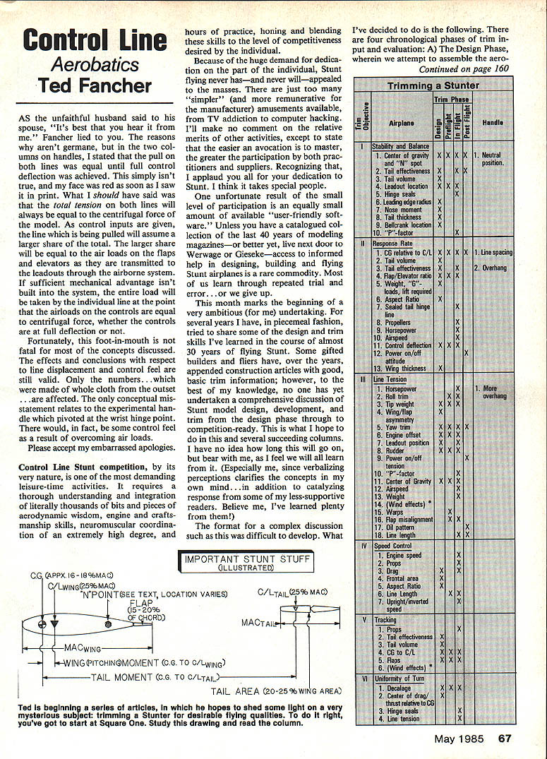
The four chronological phases of trim
There are four phases in which we make trim inputs and evaluations:
- Design Phase — assemble aerodynamic and construction information and develop basic design parameters and layouts.
- Preflight Phase — “bench-trimming”: configure the assembled airplane to the design parameters (balance, control geometry, etc.).
- Flying Phase — empirically evaluate the success of phases A and B and make inflight adjustments.
- Post-Flight Phase — evaluate subjective and objective evidence of the plane’s performance and decide further action.
The six major trim objectives
We attempt to optimize these six objectives throughout the four phases: I. Stability — does it go where it’s pointed without constant attention and exit corners flat and hard? II. Response rate — does it turn readily and controllably? III. Line tension — what causes good/bad tension and how to fix it? IV. Speed control — too fast or too slow, and how to adjust it? V. Tracking — does it fly consecutive maneuvers concentrically or wander? VI. Turn equality — does it turn equally inside and outside?
Each design parameter or inflight factor affects one or more of these objectives. In the series I’ll list parameters and indicate in which phase they should be considered, generally in descending order of influence.
Important stunt stuff (illustrated)
I’m beginning a series of articles to clarify the mysterious subject of trimming Stunters for desirable flying qualities. To do it right, you must start at square one: study drawings, study leading and trailing edges (including chines), and read widely. Paul experimented with chine-equipped models and intends to develop the idea further.
Reports and references:
- The full Goulburn Free Flight Symposium Report (29 pages), including new wind-tunnel tests from Stuttgart by Martin Simons, Power Model Trim by Stan Hines, and Lost Wax Engine Casting by Dave Sugden, is available from the New South Wales FF Society.
- The FF Champs Planbook (162 pages) contains competitors’ biographical, technical, and philosophical details, plus three-view plans. It is an excellent purchase.
Order information: NSW FF Society Committee 50 Brown St. St. Peters, NSW 2044 Australia Planbook price: $10.00 plus postage (if still available).
Assumptions and practical rules of thumb
- We assume all systems (engine, tank, weights, leadouts, etc.) are adjustable—some more easily than others.
- We assume the control system has sufficient mechanical advantage to overcome reasonably encountered airloads on the controls.
- Practical rule of thumb for modern, full-size Stunters (.35 to .60-powered):
- Use a minimum three-inch bellcrank; 3.5–4 inches strongly recommended.
- Control horns: flap pushrod at about 1.0 inch from pivot; elevator pushrod variable from 0.6 to 1.0 inch from pivot.
- Bellcrank-to-flap rod should be at least 0.75 in. from the horn pivot.
- Choose bellcrank throw (distance from bellcrank pivot to pushrod) based on desired sensitivity:
- ~0.6 in. for slow response,
- ~0.9 in. (my personal choice),
- up to ~1.25 in. for very fast response.
Finally, because C/L Stunters are flown tethered by one wingtip, we can be fairly casual about roll and yaw axes. Their importance is mainly in discussions of line tension. Pitch, however, is paramount because maneuvers are accomplished through pitch changes; we will consider pitch in detail.
Definitions and terms
- MAC (Mean Aerodynamic Chord)
If the root chord is 13 in. and the tip chord 9 in., the MAC is the station along the span where the chord is 11 in. For our purposes the MAC can be treated as the average chord and used as the reference for many parameters.
- CG (Center of Gravity)
The CG is the point about which external forces act (thrust, drag, lift). Moments (tail moments, pitching moments) are defined by their distance from the CG. Fore and aft CG location will be expressed as a distance from the leading edge of the MAC (e.g., 1.5 in. from the leading edge of a 10-in. MAC is 15% MAC).
- CL (Center of Lift)
The CL is that point on the MAC where the wing’s lift may be considered concentrated. For symmetrical airfoils CL is typically at 25% MAC and moves aft for cambered sections (for example, deflected flaps). Lift from wing and tail acts at their CLs and produces moments about the CG—like a seesaw.
- Aspect Ratio (A.R.)
Aspect ratio measures the relationship of a wing’s span to its area (or average chord). Higher aspect ratios (longer span for a given area) increase aerodynamic efficiency (better lift-to-drag) but have other handling implications: high A.R. wings typically stall at lower angles of attack and produce less drag per unit lift than low A.R. wings, which stall at higher angles and produce more drag per unit lift.
- Cl (coefficient of lift)
Cl is a non-dimensional number indicating relative lift generated by an airfoil. General behavior:
- Cl increases with increasing airspeed or increasing angle of attack (until stall).
- For a given Cl, high aspect-ratio wings achieve it at lower angles of attack than low aspect-ratio wings.
- Maximum Cl is roughly similar for high and low A.R., but low A.R. requires higher angles of attack and generates more drag per unit lift.
- High A.R. wings stall at lower angles of attack than low A.R. wings.
Whew. That sets the stage. Next month we’ll dive into the Design Phase and examine the options for developing a Stunter that meets our expectations.
Ted Fancher 158 Flying Cloud Isle Foster City, CA 94404
Transcribed from original scans by AI. Minor OCR errors may remain.

