
Control Line Aerobatics
Ted Fancher
Hi, GROUP! Probably the most consistent complaint I receive on my monthly musings is that the material I cover is too "high-tech." While I don't feel that the CL Stunt column should be considered a beginner's forum, there is nonetheless a lot of merit to those complaints.
In response, I have undertaken a project which at first thought would be a pain in the neck but which has proven to be both enjoyable and educational. I built me a Sig Twister!
Most of this and the next two columns will be a fairly detailed coverage of my experiences dealing with Stunt from the viewpoint of a beginner. Using only commercially available supplies and trying to limit a nearly uncontrollable urge to "make things better," I'm going to build, finish, and flight-trim a profile stunter appropriate for anyone from a beginning pilot (not a rank novice) to an intermediate or new advanced flier.
If I've had any luck at all with the Instamatic, several pictures should accompany the columns. These will help illustrate some of the techniques and features. Let's get the hardware out of the way first.
Hardware
- Kit: Sig Twister (kindly donated by Mike Pratt and Sig).
- Engines: Merco .35 (from Tom Dixon) and a box-stock OS .40FP.
- Fuel system: Taffinder four-ounce profile tank, modified for uniflow.
- Bellcrank: kit-supplied bellcrank was used except I substituted a Fancher Circular Crank for initial testing (no significant advantage at the beginner level; note: my fancy bellcrank caused some problems in the initial test flights).
- Covering and finishes: Sig Supercote for wing and tail; Pactra Formula U polyurethane (spray can) for fuselage.
- Trim: Top Flite MonoKote Trim sheets (sticky MonoKote).
- Hardware: Du-Bro 2.25-inch wheels and wheel retainers; Du-Bro large pinned nylon hinges; Carl Goldberg two-inch spinner.
- Fastening: Fast Threads brass threaded inserts (use 4-40s on this project) — threaded brass inserts that are installed from the visible side and act like blind mounting nuts.
Wheels and tires
When making a tire from tubing, make sure the tubing ends fit properly. When the two ends of the tube meet, glue them together. Lightly sandpaper the entire tire to get an even, flat finish. The wheel is then ready for painting, if required, and installation on your model.
Another possible source for a suitable "tire" for wheels of moderate size is vacuum cleaner parts. A suitable tire might be fashioned from the round rubber belts used in many vacuum cleaners for driving the brush. If the wheel you make is in the three- to four-inch-diameter size, you might find an appropriately sized belt.
Why the Twister?
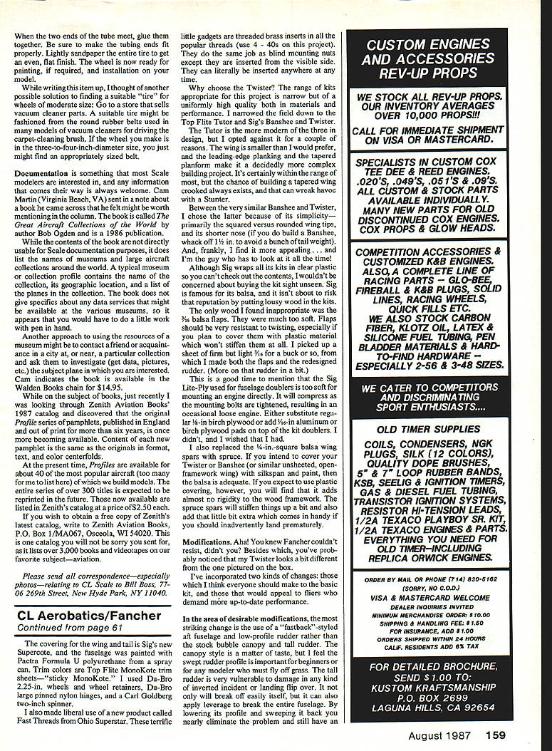
The range of kits appropriate for this project is narrow but uniformly high quality both in materials and performance. I narrowed the field down to the Top Flite Tutor and Sig's Banshee and Twister.
- The Tutor is the more modern of the three designs, but I opted against it because the wing is smaller than I would prefer and the leading-edge planking and tapered planform make it a more complex building project. A crooked tapered wing can cause havoc with a stunter.
- Between the Banshee and Twister I chose the Twister because of its simplicity — primarily the squared versus rounded wing tips — and its shorter nose (if you build a Banshee, hack off 1½ in. to avoid a bunch of tail weight).
- Frankly, I find it more appealing ... and I'm the guy who has to look at it all the time!
Sig wraps all its kits in clear plastic so you can check the contents; I wouldn't be concerned about buying the kit sight unseen. Sig is famous for its balsa and isn't about to risk that reputation by putting lousy wood in the kits.
Kit observations and recommended reinforcements
- Baggage flaps supplied in the kit were too soft. Flaps should be very resistant to twisting, especially if you plan to cover them with plastic covering which won't stiffen them. I used a sheet of firm but light 1/8-inch balsa to make both the flaps and a redesigned rudder.
- Sig Lite-Ply used for fuselage doublers is too soft for mounting an engine directly. It will compress as the mounting bolts are tightened, resulting in a loss of glue joint in the plywood engine mount. Either substitute regular 1/8-inch birch plywood or add 1/16-inch birch plywood pads on top of the kit doublers. I didn't, and I wished that I had.
- I replaced the 1/4-inch square balsa spars with spruce. If you intend to cover your Twister or Banshee with silkspan and dope, balsa spars are adequate. If you expect to use plastic covering, however, it adds almost no rigidity to the wooden framework. The spruce spars stiffen things up and add a little extra strength that helps if you inadvertently hand-launch prematurely.
Modifications
I've introduced two kinds of changes: those I think everyone should make to the basic kit, and those that would appeal to fliers who demand more up-to-date performance.
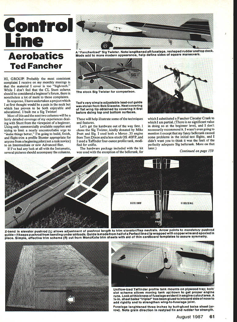
- A notable change is a "fastback"-style aft fuselage and low-profile rudder rather than the stock bubble canopy and tall rudder. The fastback profile is important for beginners or for any modeler who must fly off grass. The tall rudder is vulnerable to damage in inverted incidents or landing flips; lowering its profile and sweeping it back nearly eliminates that problem while retaining an effective rudder.
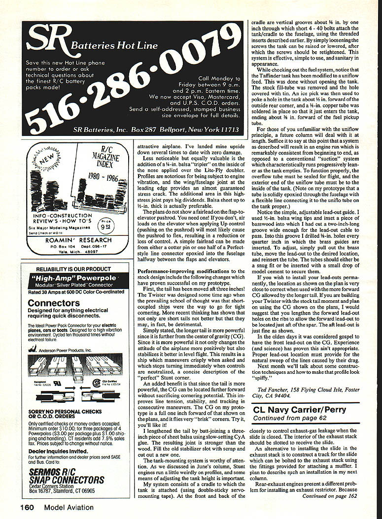
- I installed a Z-bend elevator pushrod which allows adjustment of pushrod length and trim. A simple guide keeps the pushrod from bending under airloads. The guide is made from a half-inch line clip wrapped with copper wire and epoxied in place — simple and effective.
- MonoKote trim sheets made good, thin cardboard templates to assure symmetry when cutting the trim.
- The Taffinder profile tank was uniflow-ized and mounts on a plywood tray with a bolt-and-slot scheme that allows moving the tank up or down to get proper engine runs. The tank/cradle is attached to the fuselage using short 4-40 bolts and threaded inserts. The cradle has vertical grooves about 3/16 in. by 1 in.; by simply loosening the screws the tank can be raised or lowered, after which the screws should be retightened. This system is effective, simple to use, and sanitary in appearance.
- Note the thickness of the fuselage evident in the engine cutout area. A 1/4-inch sheet balsa doubler has been glued to the inboard side of the nose to add rigidity and strengthen the wing-to-fuselage joint. The fuselage was lengthened three inches by butt-gluing balsa sheet; be sure to note the grain direction when you do this. Restyled fin and rudder details add strength and appearance.
- I used a very simple adjustable lead-out guide (stolen from Bob Gieseke) which works well. I obtained the flat wing tips covered first before doing the top and bottom surfaces; this made the tips neat and taut.
Tank mounting and uniflow conversion
While checking out the fuel system, note that the Taffinder tank has been modified to a uniflow feed without opening the tank. The stock fill tube was removed and the hole covered with tin. An ice pick was used to poke a hole in the tank about 1/8 in. forward of the outside rear corner, and a 1/16-in. copper tube was soldered in place so that it just enters the tank, ending about 1/8 in. forward of the fuel pickup tube.
For those unfamiliar with the uniflow principle: a system as described will result in an engine run that is remarkably consistent from beginning to end, as opposed to a conventional suction system which characteristically runs progressively leaner as the tank empties. To function properly, the overflow tube must be sealed for flight, and the exterior end of the uniflow tube must be to the inside of the tank. On my prototype a tube is solidly epoxied through the fuselage with a flexible line connected from it to the uniflow tube on the tank proper.
Lead-out guide and location
I used 1-inch balsa wing tips and inset a piece of basswood into which I cut a two-inch-long groove wide enough for the lead-out cable to pass. Into this groove I drilled 1/8-in. holes every quarter inch in which brass guides are inserted. To adjust, simply pull out the brass tube, move the lead-out to the desired location, and reinsert the tube. The tubes should either be a snug fit or be inserted with a small drop of model cement to secure them.
If you wish to install your lead-outs permanently, the location shown on the plan is very close to correct when used with the more forward CG allowed by the longer tail. If you are building your Twister with the stock tail moment and plan on using the CG shown on the plans, I suggest you lengthen the forward lead-out holes on the ribs to allow the forward lead-out to be located just aft of the spar. The aft lead-out is just fine as shown.
In the olden days it was considered gospel to have the front lead-out on the CG. Experience (and science) has proven this isn't appropriate. Proper lead-out location must provide for the natural sweep of the lines caused by their drag.
Next month we'll talk about some construction techniques and how to make that profile look "spiffy."
Ted Fancher 158 Flying Cloud Isle Foster City, CA 94404
Transcribed from original scans by AI. Minor OCR errors may remain.

