
Control Line: Aerobatics
Ted Fancher
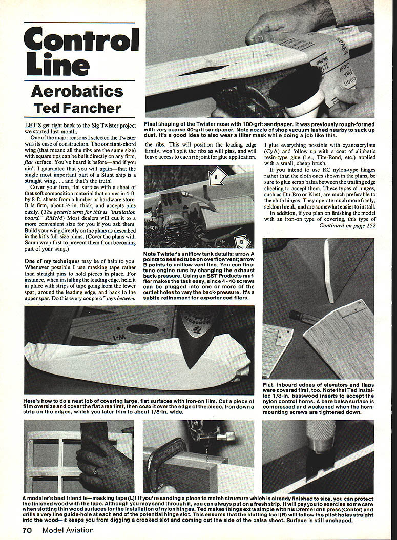
LET'S get right back to the Sig Twister project we started last month.
One of the major reasons I selected the Twister was its ease of construction. The constant-chord wing (that means all the ribs are the same size) with square tips can be built directly on any firm, flat surface. You've heard it before—and I guarantee that you will again—that the single most important part of a Stunt ship is a straight wing... and that's the truth!
Cover your firm, flat surface with a sheet of that soft composition material that comes in 4 ft. by 8 ft. sheets from a lumber or hardware store. It is firm, about 1/2 in. thick, and accepts pins easily. Most dealers will cut it to a more convenient size for you, if you ask them. Build your wing directly on the plans as described in the kit's full-size plans. (Cover the plans with Saran wrap first to prevent them from becoming part of your wing.)
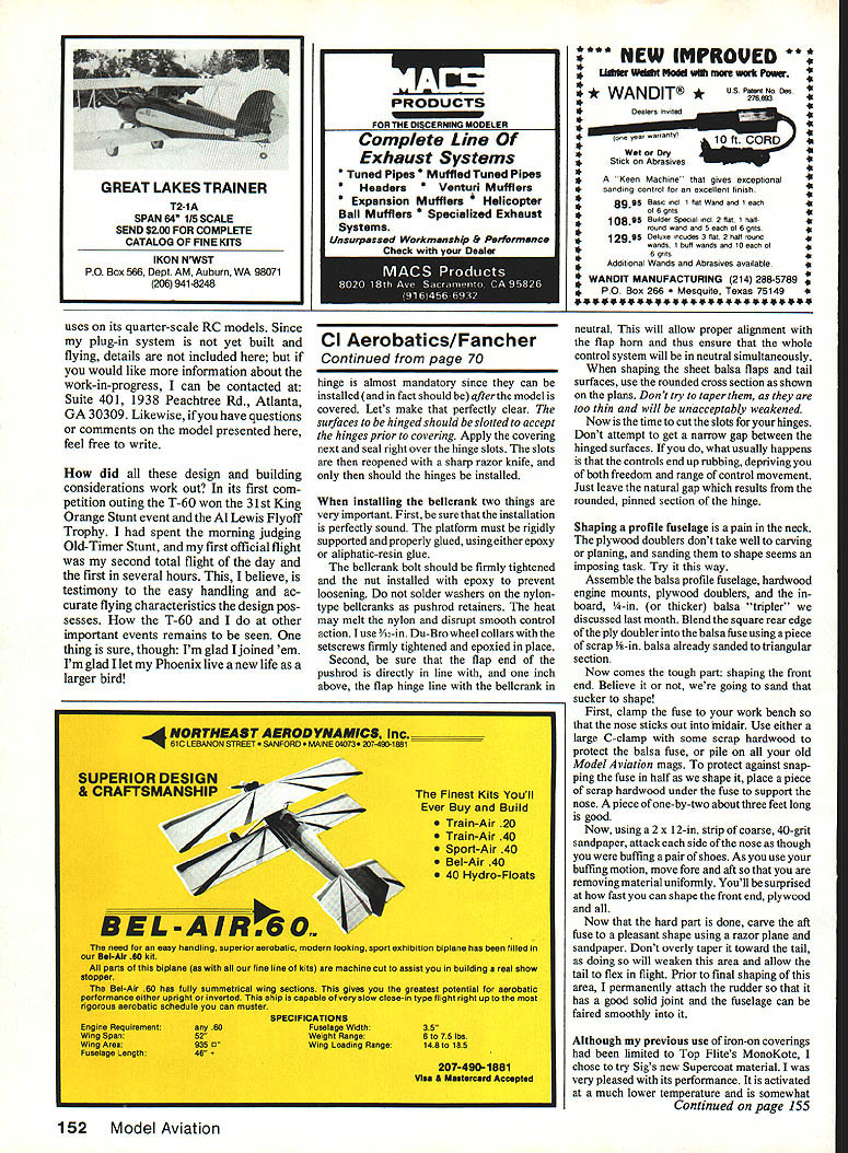
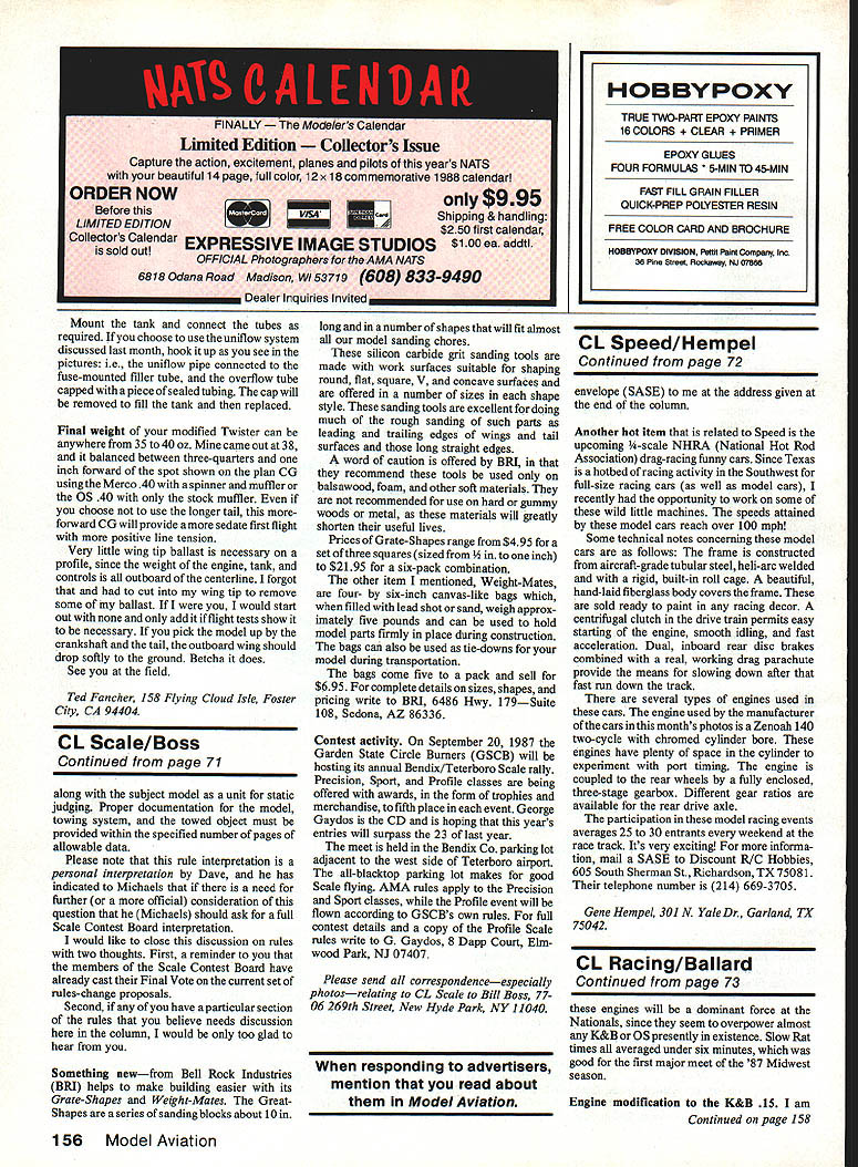
One of my techniques may be of help to you. Whenever possible I use masking tape rather than straight pins to hold pieces in place. For instance, when installing the leading edge, hold it in place with strips of tape going from the lower spar, around the leading edge, and back to the upper spar. Do this every couple of bays between the ribs. This will position the leading edge firmly, won't split the ribs as pins will, and will leave access to each rib joint for glue application.
I glue everything possible with cyanoacrylate (CyA) and follow up with a coat of aliphatic resin-type glue (i.e., Tite-Bond, etc.) applied with a small, cheap brush.
If you intend to use RC nylon-type hinges rather than the cloth ones shown in the plans, be sure to glue scrap balsa between the trailing edge sheeting to accept them. These types of hinges, such as Du-Bro or Klett, are much preferable to cloth hinges. They operate much more freely, seldom break, and are somewhat easier to install.
In addition, if you plan on finishing the model with an iron-on type of covering, follow the covering methods described below.
Covering flat surfaces and control surfaces
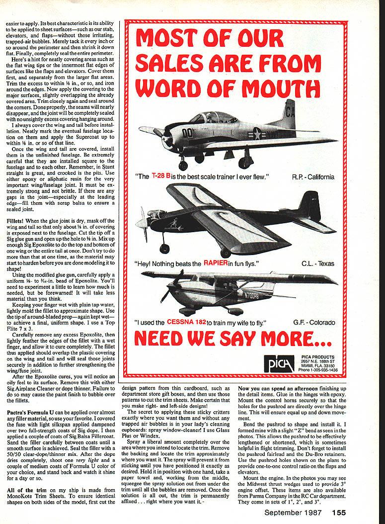
Flat inboard edges of the elevators and flaps are covered first, too. Note: I installed 1/8-in. basswood inserts to accept nylon control horns. Here's a neat job for covering large flat surfaces with iron-on film: cut a piece of film oversize to cover the flat area and the nylon control horns and the bare balsa surface. Coax the film over the edge piece, iron it down, compressing the weakened horn-strip edges; later trim about 1/8 in. wide and install the mounting screws, tightened down.
A nylon hinge is almost mandatory since they can be installed (and in fact should be) after the model is covered. The hinge slots should be cut to accept the hinges prior to covering. Apply the covering next and seal right over the hinge slots. The slots are then reopened with a sharp razor knife, and only then should the hinges be installed.
When installing the bellcrank two things are very important:
- Be sure that the installation is perfectly sound. The platform must be rigidly supported and properly glued, using either epoxy or aliphatic-resin glue. The bellcrank bolt should be firmly tightened and the nut installed with epoxy to prevent loosening. Do not solder washers on the nylon-type bellcranks as pushrod retainers. The heat may melt the nylon and disrupt smooth control action. I use Du-Bro wheel collars with the setscrews firmly tightened and epoxied in place.
- Be sure that the flap end of the pushrod is directly in line with, and one inch above, the flap hinge line with the bellcrank in neutral. This will allow proper alignment with the flap horn and thus ensure that the whole control system will be in neutral simultaneously.
When shaping the bellcrank flats and tail surfaces, use the rounded cross section as shown on the plans. Don't try to taper them, as they are too thin and will be unacceptably weakened.
Now is the time to cut the slots for your hinges. Don't attempt to get a narrow gap between the hinged surfaces. If you do, what usually happens is that the controls end up rubbing, depriving you of both freedom and range of control movement. Just leave the natural gap which results from the rounded, pinned section of the hinge.
Shaping the profile fuselage
Shaping a profile fuselage is a pain in the neck. The plywood doublers don't take well to carving or planing, and sanding them to shape seems an impossible task. Try this method.
Assemble the balsa profile fuselage, hardwood engine mounts, plywood doublers, and the firewall (or thicker balsa "tripler" we discussed previously). Blend the square rear edge of the ply doubler into the balsa fuse using a piece of scrap 3/8-in. balsa already sanded to a triangular shape.
Now comes the tough part: shaping the front end. Believe it or not, we're going to sand that sucker to shape! First, clamp the fuse to your workbench so that the nose sits out into midair. Use either a large C-clamp with some scrap hardwood to protect the balsa fuse, or pile on all your old Model Aviation magazines. To protect against snapping the fuse in half as we shape it, place a piece of scrap hardwood under the fuse to support the nose. A piece of one-by-two about three feet long is good.
Using a 2 x 12-in. strip of coarse, 40-grit sandpaper, attack each side of the nose as though you were buffing a pair of shoes. As you use your buffing motion, move fore and aft so that you are removing material uniformly. You'll be surprised at how fast you can shape the front end, plywood and all.
Now that the hard part is done, carve the aft fuse to a pleasant shape using a razor plane and sandpaper. Don't overly taper it toward the tail, as doing so will weaken this area and allow the tail to flex in flight. Prior to final shaping of this area, I permanently attach the rudder so that it has a good solid joint and the torque can be faired smoothly into it.
Covering materials and techniques
Although my previous use of iron-on coverings had been limited to Top Flite's MonoKote, I chose to try Sig's new Supercoat material. I was very pleased with its performance. It activates at a much lower temperature and is somewhat easier to apply. Its best characteristic is its ability to be applied to sheet surfaces—such as our stab, elevators, and flaps—without those irritating, trapped-air bubbles. Merely tack it every inch or so around the perimeter and then shrink it down flat. Finally, completely seal the entire perimeter.
Here's a hint for neatly covering areas such as the flat wing tips or the innermost flat edges of surfaces like the flaps and elevators. Cover them first, and separately from the larger flat areas. Trim the excess to within about 1/8 in., and iron around the edges. Now apply the covering to the major surfaces, slightly overlapping the already covered area. Trim closely again and seal around the corners. Done properly, the seams will nearly disappear, and the joint will be completely sealed with no unsightly excess covering hanging around.
I always cover the wing and tail before installation. Neatly mark the eventual fuselage location on them and apply the Supercoat up to within about 1/8 in. of that line.
Once the wing and tail are covered, install them in the unfinished fuselage. Be extremely careful that they are installed square to the fuselage and to each other. Remember, in Stunt straight is great, and crooked is the pits. Use either epoxy or aliphatic resin for the very important wing/fuselage joint. It must be extremely strong and not brittle. If there are any gaps in the joint—especially at the leading edge—fill them with scrap balsa to ensure a sealed joint.
Fillets and finishing the wing/fuselage joint
Fillets! When the glue joint is dry, mask off the wing and tail so that only about 1/8 in. of covering is exposed next to the fuselage. Cut the tip off a Sig glue gun and open up the hole to 3/16 in. Mix up enough Sig Epoxolite to do the top and bottom of one wing or the entire tail at once. Don't try to do more than that at one time, as the material may start to harden before you are done modeling it to shape!
Using the modified glue gun, carefully apply a uniform 1/8- to 3/16-in. bead of Epoxolite. You'll need to experiment a little to learn how much is needed, but be forewarned: it will take less material than you think.
Keeping your finger wet with plain tap water, lightly mold the fillet to approximate shape. Use the tip of a round-bladed prop—again kept wet—to achieve a final, uniform shape. I use a Top Flite 7x3.
Carefully remove any excess Epoxolite, then lightly feather the edges of the fillet with a wet finger, and allow it to cure completely. The fillet thus applied should overlap the plastic covering on the wing and tail and will seal those joints securely in addition to further strengthening the wing/fuse joint.
After the Epoxolite cures, you will notice an oily feel to its surface. Remove this with either Sig Airplane Cleaner or dope thinner. Failure to do so may cause the paint finish to bubble over the fillets.
Pactra's Formula U can be applied over almost any filler material, so use your favorite. I covered the fuse with light silkspan applied dampened over two full-strength coats of Sig dope. I then applied a couple of coats of Sig Balsa Fillercoat. Sand the filler carefully between coats until a smooth surface is achieved. Seal the filler with a 50/50 clear-dope/thinner mix. After the dope dries completely, shoot one very light and a couple of medium coats of Formula U color of your choice, and stand back and watch it shine for a day or so.
Trim application
All of the trim on my ship is made from MonoKote Trim Sheets. To ensure identical shapes on both sides of the model, first cut the design pattern from thin cardboard, such as department store gift boxes, and then use those patterns to cut the trim sheets. Make certain that you mark right- and left-side designs!
The secret to applying these sticky critters exactly where you want them and without any trapped air bubbles is in your lady's cleaning cupboards: spray window cleaner! I use Glass Plus or Windex.
- Spray a liberal amount completely over the area where you intend to locate the trim.
- Remove the backing and locate the trim approximately where you want it. The spray will prevent it from sticking until you have positioned it exactly as desired.
- Hold it in position with one hand, take a paper towel and, working from the middle, squeeze the spray solution out from under the trim until all the bubbles are removed.
- Once the solution is all out, the trim is permanently affixed—right where you want it.
Final assembly and adjustments
Now you can spend an afternoon finishing up the detail items. Glue in the hinges with epoxy. Mount the control horns securely so that the holes for the pushrod are directly over the hinge line. This will ensure equal up and down movement.
Bend the pushrod to shape and install it. I formed mine with a slight "Z" bend as seen in the photos. This allows the pushrod to be effectively lengthened or shortened, which is sometimes helpful in flight trimming. Don't forget to install the bearing for the bellcranks and the Du-Bro retainers.
I use Du-Bro clevises.
Mount the tank and connect the tubes as required. If you choose to use the uniflow system discussed last month, hook it up as you see in the pictures; i.e., the uniflow pipe connected to the fuse-mounted filler tube, and the overflow tube capped with a piece of sealed tubing. The cap will be removed to fill the tank and then replaced.
Final weight of your modified Twister can be anywhere from 3-1/2 to 4 oz. Mine came out at 3.8 oz., and it balanced between 3/4 and 1 in. forward of the spot shown on the plan when using the Merco .40 with a spinner and muffler or the OS .40 with only the stock muffler. Even if you choose not to use the longer tail, this more-forward CG will provide a more sedate first flight with more positive line tension.
Very little wing-tip ballast is necessary on a profile, since the weight of the engine, tank, and controls is all outboard of the centerline. I forgot that and had to cut into my wing tip to remove some of my ballast. If I were you, I would start out with none and only add it if flight tests show it to be necessary. If you pick the model up by the crankshaft and the tail, the outboard wing should drop softly to the ground. Betcha it does.
See you at the field.
Ted Fancher 158 Flying Cloud Isle Foster City, CA 94404
Transcribed from original scans by AI. Minor OCR errors may remain.

