
Control Line: Aerobatics
Ted Fancher 158 Flying Cloud Isle Foster City, CA 94404
Fuel Tanks
LET'S TALK about fuel tanks. While seemingly a simple container whose sole purpose is to keep raw fuel from spilling all over the beautiful finish on our Stunters, when looked at more closely it can be seen that tanks are intimately involved in the success or failure of our efforts in the Stunt circle. The design of the tank, its location in the airplane, and the manner in which it is plumbed all affect the way the engine runs and, therefore, the way the airplane flies.
There are two major types of fuel tanks in common use for Stunt ships: plastic RC tanks and metal tanks. The manner and type of construction is not particularly significant since this part of the tank—the skin, if you will—has only one function: containing the fuel. The only important requirement is that there be no leaks in the container.
The shape of the tank is also less critical than some might imagine. The most important task of the tank shape is to ensure that fuel is available to the engine pickup tube until all but the very last few drops of fuel are consumed.
The classic wedge style, wherein the outboard side is formed into a “V” shape, is somewhat helpful in ensuring that the entire fuel load is burned. However, until the fuel is nearly exhausted this style tank's performance will be no better than a rectangular tank with no “V.”
The ideal cross section of a Stunt tank should be somewhat wider than it is tall. The classic cross section of metal tanks is 1 inch high by 2 inches wide, which results in almost exactly one ounce of fuel per inch of tank length. Recently, tanks for some of the larger engines have gone as deep as 1-1/2 inches to allow more quantity in a given length. There is no apparent difference in performance.
I have also seen (and owned) tanks to which additions had been tacked on to the top or bottom to gain additional volume. Again, this seems to have no adverse effect on performance.
If a tank's type of construction and shape have little effect on performance, what is important? Location and plumbing are the big two—that is, where the tank is located in relation to the engine and the airplane centerline, and how the various tubes—fuel feed line, tank vent, overflow, etc.—are positioned in the tank.
Location
The vertical location of a gas tank in relation to the engine can be altered to equalize engine speed in upright and inverted flight. If a tank is below the “proper” position, the engine will have to use more effort to draw the fuel than if the tank were mounted higher. This will result in the engine running leaner (at a given needle setting). If you then go inverted, the tank will be above its “proper” location, and the engine will run richer. Stunt tanks should be made removable and adjustable so the tank can be moved up or down to eliminate any difference in engine speed between upright and inverted flight.
The fore-and-aft location is important because the farther aft the tank is located, the farther “uphill” the engine will have to draw the fuel when the plane is in a climb. If this distance is excessive, it will cause the engine to lean out. The tank should generally be mounted as close to the engine as can be done comfortably.
Because we fly in a circle, the centrifugal force developed on the model causes the fuel to empty from one side to the other (the fuel pickup tube sucks fuel from the side of the tank nearest to the outside of the flight circle), not from top to bottom. As fuel is burned, the remainder is forced against the outside wall until it is depleted. The fuel is thus seeking the point in the tank furthest from the center of the circle.
If your tank is mounted parallel to the centerline of the airplane (looking down on the model), and the nose of the plane is pointed out slightly to maintain line tension, the fuel pickup tube at the outboard rear corner of the tank may be uncovered while fuel still remains. This arrangement often results in an on-again/off-again engine; some engines will quit. Eliminate the problem by mounting the tank at a slight angle, ensuring that the outboard aft corner is always further from the circle's center than the front outboard corner.
Full-bodied Stunters automatically position the tank directly behind the engine; profile designs place the tank somewhat outboard. Stunt engines have adequate fuel draw to overcome the resulting need to draw fuel back against centrifugal force; less ideal arrangements use tanks pierced by two tubes—one for fuel and one for air. In practical use, however, we generally use three tubes.
Tank Plumbing
The three common tubes are:
- A fill/vent (and/or uniflow) tube which comes to the top of the tank and is used as the vent during normal operation.
- A fuel pickup tube which feeds the fuel to the engine.
- An overflow pipe through which excess fuel is drained when the tank is completely filled during refueling.
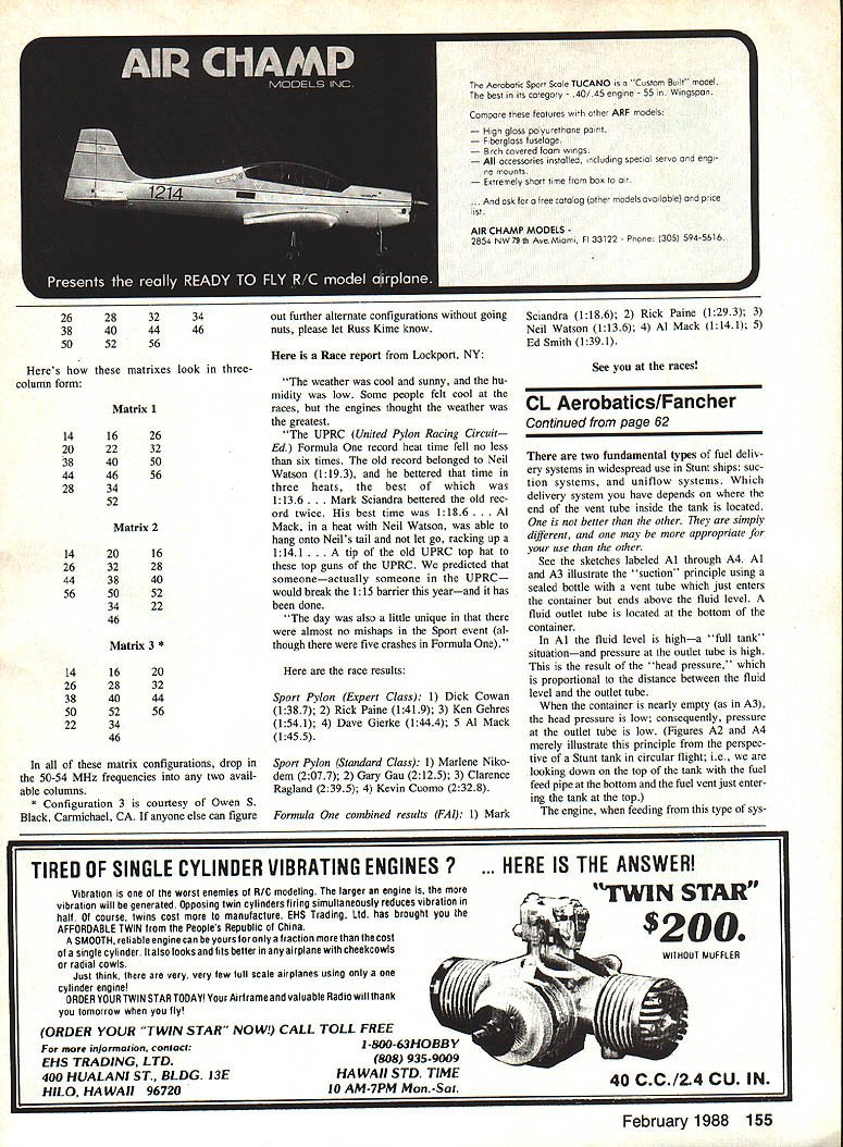
The uniflow system looks much the same as the basic suction system, except that the end of the vent pipe (the “uniflow pipe”) is brought very near to the mouth of the outlet tube. It is claimed that this causes the fuel pressure to be independent of the depth of fuel in the tank. The uniflow vent tube must be the only source of vent air in the tank.
Typical locations (nearly universal):
- The fuel pickup tube exits the front outboard corner where it is connected to the engine. The pickup should extend to the outboard rear corner, halfway between the top and bottom of the tank.
- The overflow tube comes out the bottom toward the front of the tank and exits near the top inboard corner.
- The fill/vent or uniflow tube comes to the top of the tank.
The manner in which the vent/uniflow tube is installed will determine the type of fuel delivery system and how the engine will run as fuel is drawn from the tank.
Fuel Delivery Systems
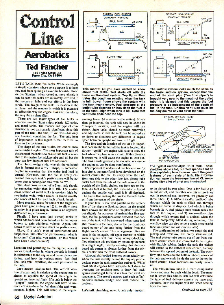
There are two fundamental types of fuel delivery systems in widespread use in Stunt ships: suction systems and uniflow systems. Which delivery system you have depends on where the vent tube ends inside the tank. One is not better than the other; they are simply different, and one may be more appropriate for your ship than the other.
- Suction system: The vent tube just enters the container but ends above the fluid level. A fluid outlet tube is located at the bottom of the container. When the tank is full the pressure at the outlet is high (head pressure). When nearly empty the head pressure is low. The engine will run richer when the tank is full and leaner as the tank empties. The engine will also run richer when the tank is mounted higher and leaner when mounted lower. In circular flight the fuel feed will change as the fuel level relative to the pickup tube changes.
- Uniflow system: The vent tube extends deep into the tank, nearly to the fluid outlet tube or adjacent to the fuel pickup tube. As long as there are no other air sources into the system, the pressure at the fluid outlet is equal to the distance (head) between the end of the uniflow tube and the outlet, regardless of total fuel amount. This keeps the engine running at a consistent speed without the leaning-out tendency of the suction system.
Note: Once the fluid level drops below the uniflow tube, the system reverts to straight suction. To ensure uniflow remains effective, place the uniflow tube very close to the fuel pickup—about 1/8 inch forward of (and directly inboard of) the pickup tube is normal.
If the uniflow tube is located outboard of the fluid outlet, there will be no head pressure; flow then depends on engine suction. As far as the engine is concerned, the end of the uniflow tube is the effective “tank.” Move that end, and the engine “thinks” the entire tank has moved.
Using the Two Systems to Trim Performance
Use the two delivery systems to help trim the airplane to optimum performance.
- If your ship is slightly heavy and you want a bit more power late in the flight, use the suction system. It provides more “zip” toward the end of the pattern because the engine will run richer as head pressure changes.
- If you prefer a steady engine speed throughout the flight, use uniflow. Uniflow allows you to use a larger venturi (for more engine power) without fear the engine will starve at the end of the run.
All of my tanks are set up to accommodate either uniflow or suction. By capping the overflow tube, I have a normal uniflow system. If I cap the uniflow tube and leave the overflow open, the system becomes suction. For uniflow to work, the overflow must be capped. If both tubes are left uncapped, the system will act as a pure suction system.
As a matter of policy, I always cap either the uniflow or overflow tube. In addition, all of my tubes are bent into the slipstream to ensure that the airflow doesn't create a siphoning action and draw out raw fuel. If you are using a commercial tank with short vents, cut a short piece of fuel tubing at a 45-degree angle and install it on the vent tube facing into the wind. This is important, since a little siphoning on the ground will increase in the air and create negative pressure in the tank, which may cause the engine to run lean.
Other Considerations
- Muffler pressure: Try it out. It may or may not be superior. It is no cure-all, but it can generally improve engine consistency by maintaining a more constant pressure at the vent tube. It is more likely to help a suction system than a uniflow system.
- High-pressure systems (bladders, crankcase pressure taps): Generally not useful in Stunt ships. They are more appropriate for applications seeking maximum rpm with intakes too large to provide adequate suction. A classic four-cycle Stunt run doesn't respond well to such systems.
- Tank mounting: Tanks should be mounted solidly. Fuel foaming should not be a problem if the nose of the ship is properly constructed and vibration is kept to a minimum. If a tank isn't positively located, it will move—Murphy's law applies.
Gotta go now.
Fly Stunt!
Transcribed from original scans by AI. Minor OCR errors may remain.

