
Control Line: Aerobatics
Ted Fancher 158 Flying Cloud Isle Foster City, CA 94404
Introduction
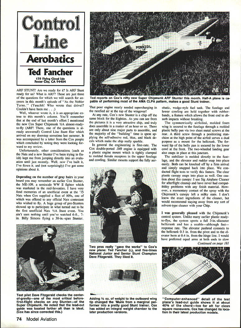
ARF Stunt — are we ready for it? Is ARF Stunt ready for us? Those were a few of the questions I wanted to answer after receiving a Cox Super Chipmunk almost-ready-to-fly (ARF) Control Line Stunt model last summer. A letter from Cox accompanied the plane, noting they looked forward to my review. Other commitments delayed my evaluation until recently. I’ve built it, flown it, and have some opinions.
Depending on the number of gray hairs in your beard, you may remember an earlier Cox Stunter, the ME‑109, marketed in the mid‑1970s. I have fond memories of an unofficial event at the ’75 Nats when Cox supplied a fleet of 109s. Cox’s new Super Chipmunk is a chip off that same block for the Eighties.
Assembly and construction
- The model is attractive and assembles quickly — truly in about an hour. There are roughly nine major parts; most of the time is spent applying the self-adhesive red, blue, and black decals.
- Engineering is generally first‑rate. The Cox double‑ported .049 engine uses a plastic engine mount clamped to molded female receptors in the upper fuselage and cowling. Similar mounts support the wedge-style fuel tank.
- The fuselage and lower cowling are held together with rubber bands, allowing the front end to absorb impacts without breaking literally in half.
- The molded foam wing is airfoiled and secured to the fuselage through a molded plastic belly pan via two sheet‑metal screws; a third screw through a positioning stanchion at the high point of the airfoil mounts the bellcrank. The belly pan is secured by the lower cowl at the front. The two‑wheeled landing gear snaps into place there as well.
- The stabilizer is molded to the fuselage. The elevator and rudder snap into place and can be knocked off in a firm arrival and snapped back on. The clear plastic canopy also snaps into place.
Canopy caution: avoid solvent‑type cleaners. I used a spray cleaner once and the canopy developed a milky stain. Use care with any spray or solvent near the canopy.
Decal tips:
- Apply decals before assembly; it makes the job much easier.
- Press decals firmly around molded details (panel lines, rivets) to prevent fuel seepage. I used my fingernail; heavier-use planes may need a tool.
- Skip the white canopy outline — on my plane it started to peel after one flight.
- There is a top and bottom to the foam wing. Be careful: once a trim sheet sticks to the foam it’s very difficult to reposition. I had to seal lifted edges with clear Fascal.
Control system and initial trim observations
- The control system is a definite improvement over many earlier plastic ready‑to‑fly models. It uses a full 3‑in. diameter bellcrank and has usable — although fast — response.
- The elevator pushrod connects to the bellcrank 0.5 in. from the pivot and to the elevator horn 0.4 in. from the hinge line. I would have preferred equal arm lengths to slow the response somewhat.
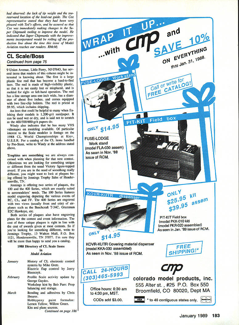
- A clevis, two‑piece lead‑out guide locates the lead‑outs at about 40% chord — too far aft for clean square maneuvers. On later production models Cox has changed this location.
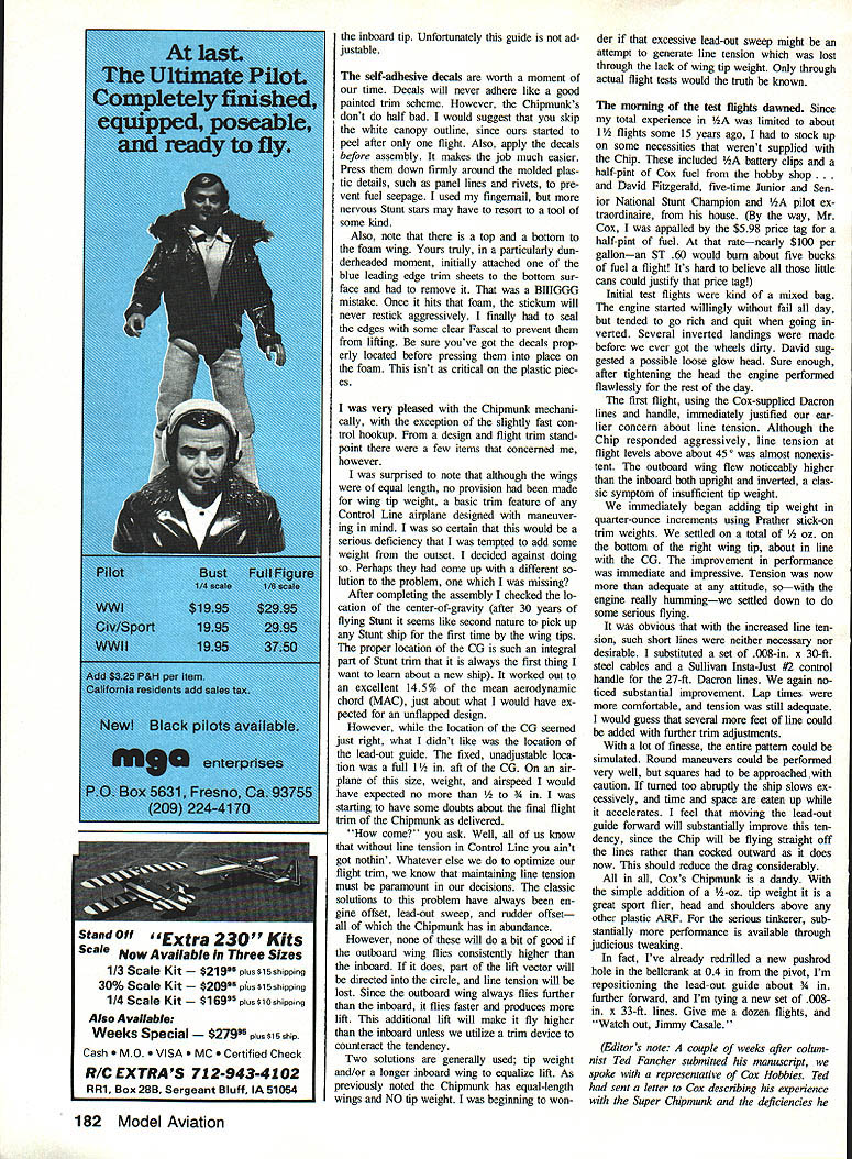
- I was surprised that although the wings are the same length, no provision was made for wing tip weight — a basic trim feature on maneuvering Control Line airplanes. I checked the center‑of‑gravity (CG) after assembly: it worked out to about 1/4 in. aft of the mean aerodynamic chord (MAC), which is reasonable for an unflapped design.
- However, the fixed lead‑out guide was about 1/8 in. aft of the CG. On a plane of this size and speed I’d expect the lead‑outs to be no more than 1/8 to 3/16 in. aft of the CG. That, combined with no tip weight, raised concerns about line tension and final flight trim.
Why this matters: without line tension you have nothing. Engine offset, lead‑out sweep, and rudder offset can help, but none of those compensate if the outboard wing consistently flies higher than the inboard wing. The outboard wing flies farther, therefore faster, producing more lift and tending to fly higher — which reduces line tension. Typical solutions are tip weight and/or a longer inboard wing to equalize lift; the Chipmunk as delivered had neither.
Flight tests
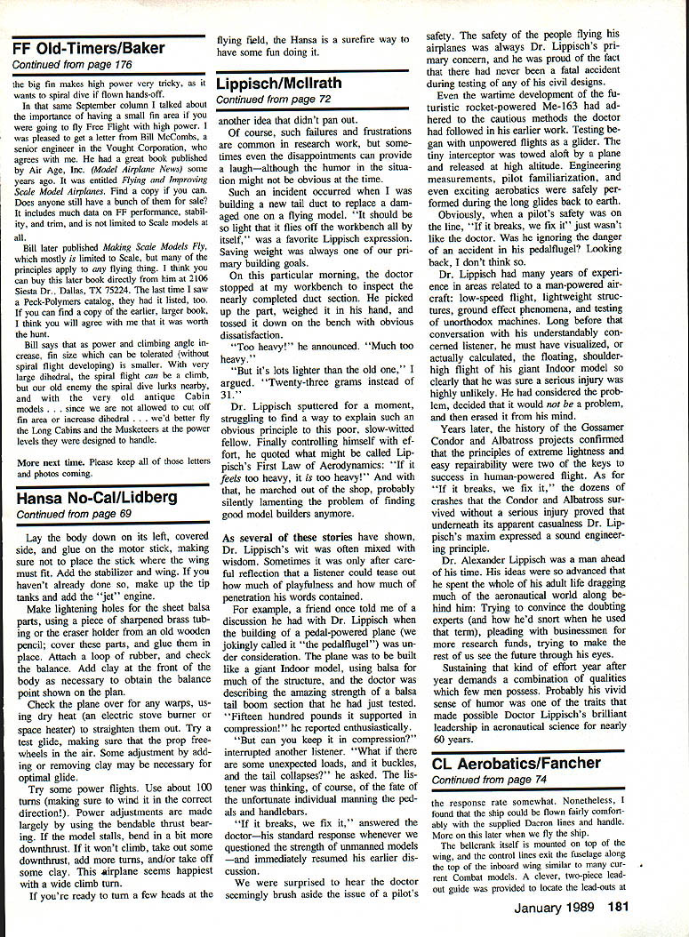
- Preparation: My 1/2A experience was limited, so I brought along 1/2A battery clips, a half‑pint of Cox fuel, and experienced pilot David Fitzgerald (five‑time Junior and Senior National Stunt Champion).
- Engine: The Cox .049 started reliably but went rich and quit when inverted. David suggested a loose glow head; tightening the head fixed the problem and the engine ran flawlessly thereafter.
- Initial flights with the supplied Dacron lines (27 ft.) and handle confirmed insufficient line tension. The outboard wing flew noticeably higher than the inboard in both upright and inverted flight — classic insufficient tip weight symptoms.
- We added tip weight in quarter‑ounce increments using Prather stick‑on trim weights. We settled on 1/2 oz. on the bottom of the right wing tip, about in line with the CG. The improvement was immediate: tension became adequate at any attitude and the plane flew much better.
- Line and handle upgrade: I substituted .008‑in. x 30‑ft. steel cables and a Sullivan Insta‑Just #2 control handle. Lap times were more comfortable and tension remained good. I suspect several more feet of line could be used with additional trim.
- Maneuvering: With finesse the entire stunt pattern could be imitated. Round maneuvers were very good. Squares required caution: if turned too abruptly the ship slows excessively and needs time/space to accelerate. Moving the lead‑out guide forward should help by making the Chipmunk fly straighter on the lines rather than canted outwards, reducing drag.
Overall verdict from flight testing: with the simple addition of a 1/2‑oz. tip weight the Chipmunk is a great first flyer, far above other plastic ARFs. For serious competitors, a few professional trim adjustments will push it to higher performance.
Modifications and recommendations
What I changed and recommend:
- Pushrod: I redrilled a new pushrod hole in the bellcrank at 0.4 in. from the pivot (originally 0.5 in.) to slow the elevator response.
- Lead‑outs: I repositioned the lead‑out guide about 3/8 in. further forward.
- Lines and handle: I tied in a new set of .008‑in. steel cables (30 ft.) and used a Sullivan Insta‑Just #2 handle.
- CG: I adjusted the setup to swing the CG slightly more nose‑down.
- Wing incidence: I plan to test a slight asymmetric wing incidence by reducing the incidence of the right wing slightly.
Other recommendations and notes:
- Add about 1/2 oz. of tip weight (or use the later production models with an integral weight chamber).
- Move the lead‑out guide forward from 40% chord to improve square maneuvers and reduce drag.
- Apply decals before assembly and take care with the foam surface placement.
- Avoid solvent cleaners on the canopy.
Editor’s note
A couple of weeks after Ted submitted his manuscript, we spoke with a Cox Hobbies representative. Ted had reported the lack of tip weight and the too‑rearward location of the lead‑out guide. The Cox representative said they appreciated Ted’s efforts and were immediately making tooling changes to improve the model. They indicated Super Chipmunks with the improvements (including an integral weight chamber and a revised lead‑out location) would be rolling off the production line around the time this issue reaches readers. — RMcM
Transcribed from original scans by AI. Minor OCR errors may remain.

