
Control Line: Aerobatics
Ted Fancher 158 Flying Cloud Isle Foster City, CA 94404
Fuel tank placement — the question
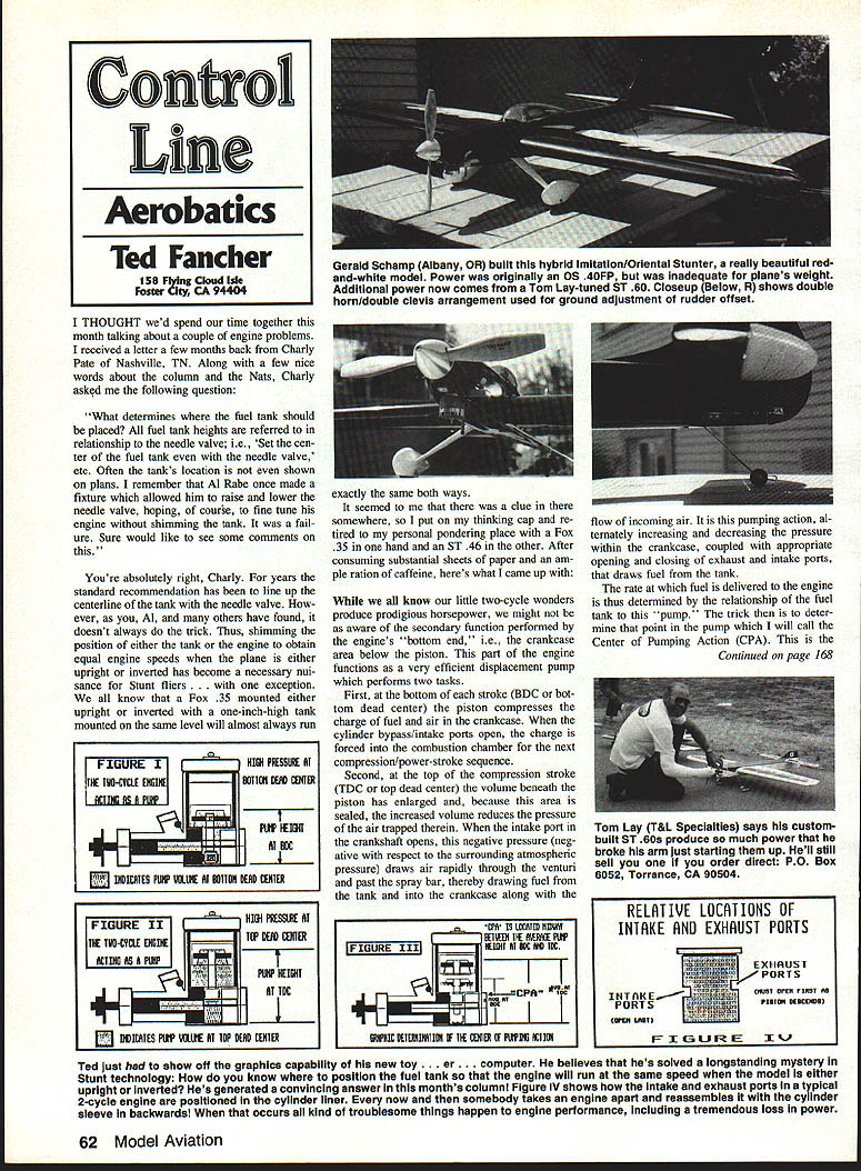
A few months ago Charly Pate of Nashville, TN wrote asking: What determines where the fuel tank should be placed? Conventional advice is to line up the centerline of the fuel tank with the needle valve, but that doesn't always work. Many fliers end up shimming either the tank or the engine until the model runs the same upright and inverted. As an example, a Fox .35 with a one-inch-high stunt tank mounted level with the engine mounts will usually run the same right side up or inverted — a clue worth investigating.
Pumping action of the crankcase and the CPA
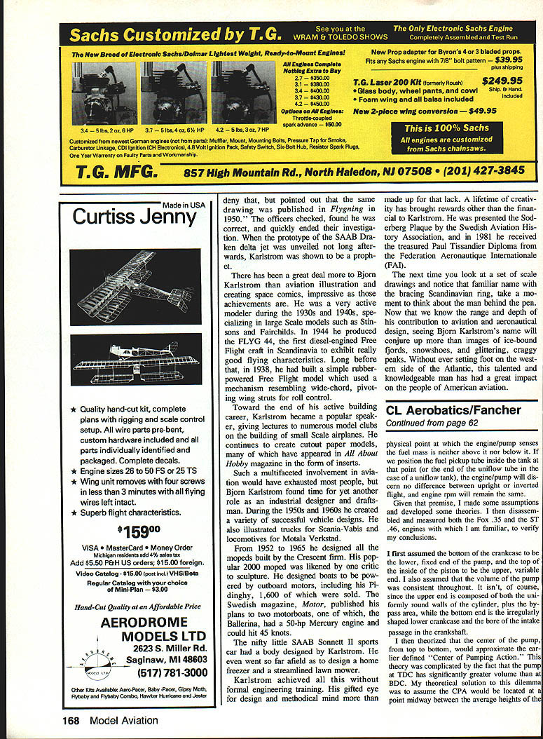
Two-stroke engines use the crankcase below the piston as a displacement pump. It performs two complementary functions:
- At BDC (bottom dead center) the piston compresses the charge in the crankcase; when the bypass/intake ports open, that charge flows into the combustion chamber for the next cycle.
- At TDC (top dead center) the volume beneath the piston increases, reducing pressure in the crankcase. When the crankcase intake opens this negative pressure draws air through the venturi and past the spray bar, drawing fuel from the tank into the crankcase.
The rate at which fuel is delivered depends on the relationship between the fuel tank and this pump. I call the point in the pump where the engine "senses" the fuel mass as neither above nor below it the Center of Pumping Action (CPA). If the fuel pickup or the end of a uniflow tube is located at the CPA, the engine should run the same upright and inverted.
The CPA is influenced by port timing, exhaust timing, piston shape, and crankcase shape, and it shifts with engine speed. Determining it precisely requires disassembly and measurement, so I made a practical approach using familiar engines (Fox .35 and ST .46) to test the idea.
Assumptions and measurement method
- Treat the bottom of the crankcase as the fixed lower end of the pump and the top of the piston as the upper, variable end.
- Measure pump depth at BDC (from the bottom of the crankshaft web at the crankpin location to the top inside of the piston).
- Pump depth at TDC = pump depth at BDC + piston stroke.
- Average pump depth = (pump depth at BDC + pump depth at TDC) / 2; the midpoint of that average is the CPA measured from the bottom datum.
- Because engine mounts are on the crankshaft centerline, subtract half the diameter of the backplate opening from the CPA (measured from the same datum) to get the CPA height above the engine mounts — the recommended pickup/uniflow location.
Calculations — Fox .35
Engine data:
- Displacement: 0.352 cu. in.
- Bore: 0.800 in.
- Stroke: 0.700 in.
- Diameter of backplate opening: 1.05 in.
Pump measurements and calculations:
- Pump depth at BDC: 1.700 in.
- Pump depth at TDC: 2.400 in.
- Average pump depth: 2.050 in.
- Midpoint of average pump depth (CPA): 1.025 in.
- Subtract half backplate opening (0.525 in): CPA above engine mounts = 0.500 in (1/2 in)
Observation: A standard one-inch stunt tank has its pickup tube exactly halfway up the tank (0.5 in above mounts), matching this CPA — explaining why the Fox .35 and a 1" stunt tank often run equally well upright and inverted.
Calculations — ST .46
Engine data:
- Displacement: 0.46 cu. in.
- Bore: 0.865 in.
- Stroke: 0.780 in.
- Diameter of backplate opening: 1.10 in.
Pump measurements and calculations:
- Pump depth at BDC: 1.787 in.
- Pump depth at TDC: 2.569 in.
- Average pump depth: 2.178 in.
- Midpoint of average pump depth (CPA): 1.089 in.
- Subtract half backplate opening (0.550 in): CPA above engine mounts ≈ 0.539 in (≈0.54 in)
Conclusion from ST: The CPA suggests either a slightly thicker tank or shimming the tank off the mounts to match the calculated CPA. On the ST the needle valve height is over 0.800 in. off the mount; mounting a tank level with the needle valve would usually make the engine run rich inverted and lean upright.
Practical guidance and limitations
- The CPA method gives a sound starting point for locating a tank, but because of the many variables (top- and bottom-end volumes, port shapes/timing, etc.) it remains an approximation. Final trimming (shimming tank/engine, adjusting pickup) is usually necessary.
- Determining CPA precisely is clumsy and requires disassembly and measurements that themselves are approximate.
A simpler rule of thumb
Based on the limited sampling of common two-stroke stunt engines (Fox .35, ST .46, and an old OS Max .35 stunt), a good practical starting point is:
- Align the fuel pickup tube or the uniflow vent with the top of the backplate opening.
This simple starting position agreed with calculated CPAs and real-world behavior within a few hundredths of an inch for the engines checked. Since two-stroke stunt engine layouts are similar, there should be little variation for other engines of similar design.
- Users of four-cycle engines: determine the CPA based on the volume of the combustion chamber at TDC and BDC, because the top end produces the pumping action in four-stroke designs.
If this advice isn't helpful, tell everybody you heard it from Urnowski. (Just kidding, Windy. Please don't send your alligators after me.)
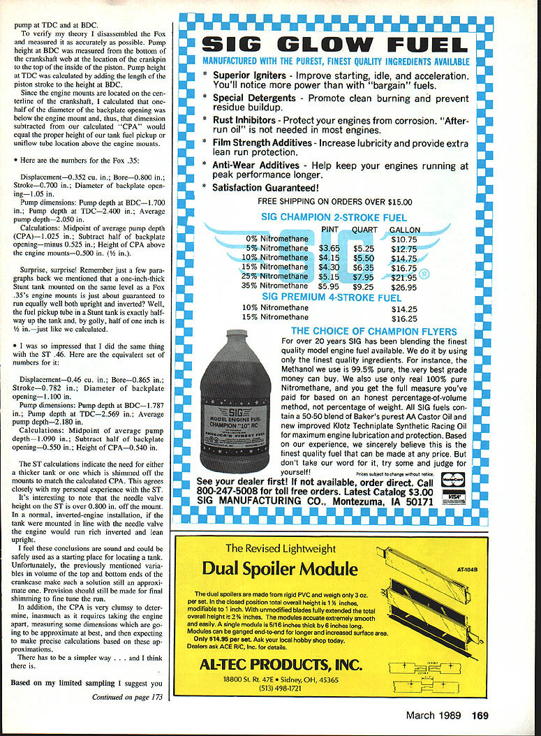
Case study: a backwards cylinder liner (Paul Pomponio's ST .46)
I examined a used ST .46 that a young friend, Paul Pomponio, had trouble starting. It eventually ran but with little power and the lower crankcase became extremely hot. Normally the crankcase runs cool because of cooling by the incoming fuel/air charge.
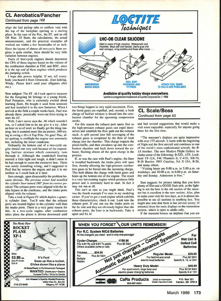
On disassembly the problem was obvious: the cylinder liner had been installed rotated 180°. The exhaust ports were aligned with the crankcase intake bypasses, and the intake ports were aligned with the exhaust.
Why this causes trouble:
- On a correctly assembled two-stroke, the exhaust ports open slightly earlier than the intake ports so high-pressure exhaust gases can exit and establish flow out the exhaust stack; the intake opens a split second later to scavenge and refill the chamber with fresh charge.
- If the liner is backwards the intake opens first, allowing high-pressure combustion gases into the incoming charge. This dilutes the fresh charge with burnt gases, heats the bottom end, and produces poor power and very hard starting. In some cases the engine will not run at all.
This error is not extremely rare — Paul's was the fourth example I've seen. If you have a used engine with poor power, excessive heat in the lower crankcase, or starting difficulty, check the liner orientation:
- Look into the exhaust port. If you can see the intake ports on the far side and they are higher than the exhaust ports, the liner is installed backward.
- If so, disassemble and reinstall the liner correctly.
(See Figure IV for a generic cylinder liner showing intake and exhaust port relative heights.)
Final notes
- The CPA concept explains why some tank placements work well inverted and upright, and gives a rational method for estimating pickup height.
- Use the simple rule of thumb (align pickup with top of backplate opening) as a starting point, then fine-tune by test flights and shimming as required.
- Check used engines for proper liner orientation if they run hot, weak, or are hard to start.
Transcribed from original scans by AI. Minor OCR errors may remain.

