
Aerobatics
Wynn Paul
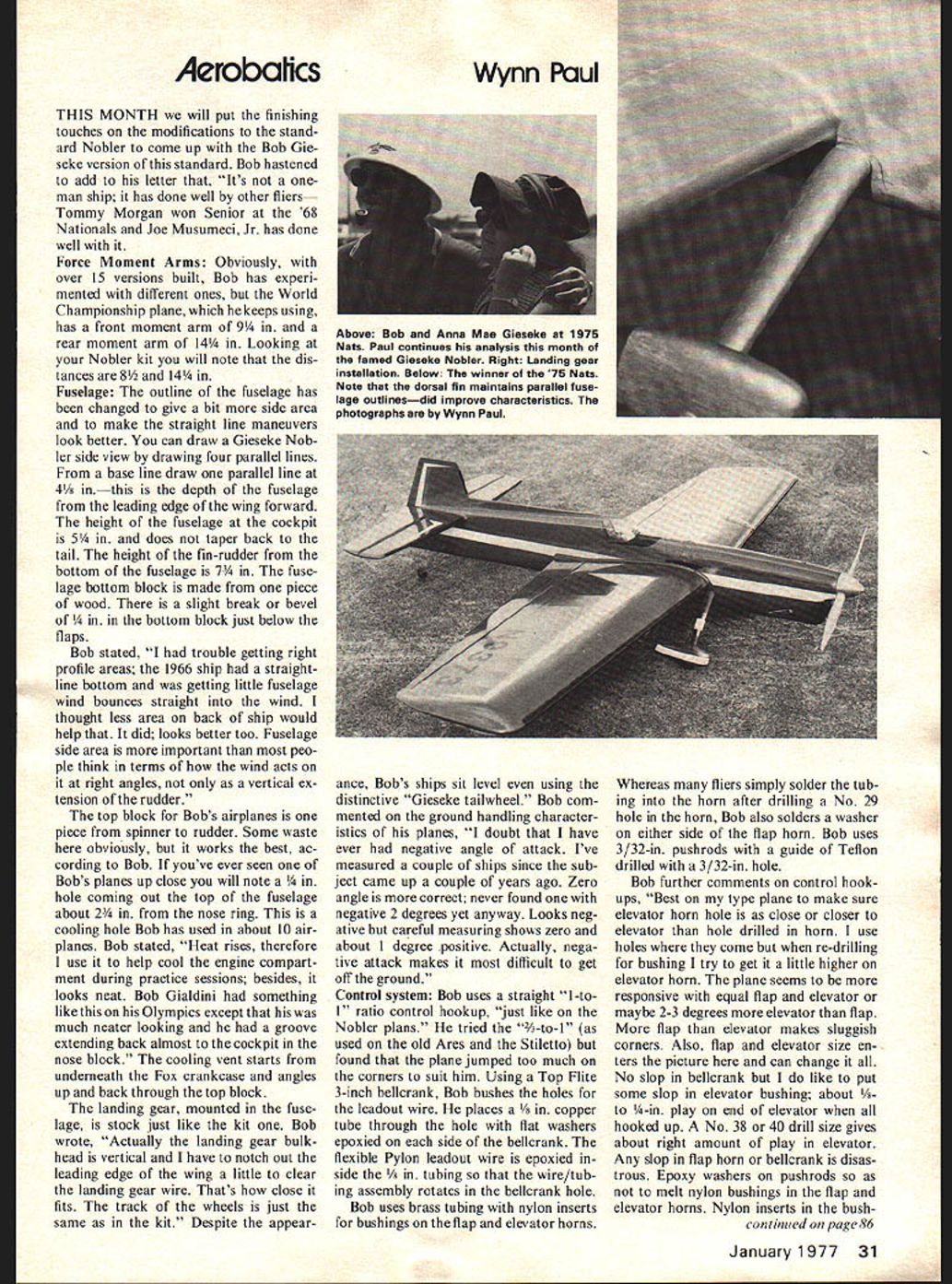
THIS MONTH we will put the finishing touches on the modifications to the standard Nobler to come up with the Bob Gieseke version of this standard. Bob hastened to add to his letter that, "It's not a one-man ship; it has done well by other fliers—Tommy Morgan won Senior at the '68 Nationals and Joe Musumeci, Jr. has done well with it."
Force Moment Arms: Obviously, with over 15 versions built, Bob has experimented with different ones. But the World Championship plane, which he keeps using, has a front moment arm of 9 1/4 in. and a rear moment arm of 14 1/4 in. Looking at your Nobler kit you will note the distances are 8 1/2 and 14 1/4 in.
Fuselage: The outline of the fuselage has been changed to give a bit more side area and to make the straight line maneuvers look better. You can draw a Gieseke Nobler side view by drawing four parallel lines. From a base line draw one parallel line at 4 1/4 in.—this is the depth of the fuselage from the leading edge of the wing forward. The height of the fuselage at the cockpit is 5 1/4 in. and does not taper back to the tail. The height of the fin-rudder from the bottom of the fuselage is 7 3/4 in. The fuselage bottom block is made from one piece of wood. There is a slight break or bevel of 1/4 in. in the bottom block just below the flaps.
Bob stated, "I had trouble getting right profile areas; the 1966 ship had a straight-line bottom and was getting little fuselage wind bounces straight into the wind. I thought less area on back of ship would help that. It did; looks better too. Fuselage side area is more important than most people think in terms of how the wind acts on it at right angles, not only as a vertical extension of the rudder."
The top block for Bob's airplanes is one piece from spinner to rudder. Some waste here obviously, but it works the best, according to Bob. If you've ever seen one of Bob's planes up close you will note a 1/4 in. hole coming out the top of the fuselage about 2 3/4 in. from the nose ring. This is a cooling hole Bob has used in about 10 airplanes. Bob stated, "Heat rises, therefore I use it to help cool the engine compartment during practice sessions; besides, it looks neat. Bob Gialdini had something like this on his Olympics except that his was much neater looking and he had a groove extending back almost to the cockpit in the nose block." The cooling vent starts from underneath the Fox crankcase and angles up and back through the top block.
The landing gear, mounted in the fuselage, is stock just like the kit one. Bob wrote, "Actually the landing gear bulkhead is vertical and I have to notch out the leading edge of the wing a little to clear the landing gear wire. That's how close it fits. The track of the wheels is just the same as in the kit." Despite the appearance, Bob's ships sit level even using the distinctive "Gieseke tailwheel." Bob commented on the ground handling characteristics of his planes, "I doubt that I have ever had negative angle of attack. I've measured a couple of ships since the subject came up a couple of years ago. Zero angle is more correct; never found one with negative 2 degrees yet anyway. Looks negative but careful measuring shows zero and about 1 degree positive. Actually, negative attack makes it most difficult to get off the ground."
Control system: Bob uses a straight "1-to-1" ratio control hookup, "just like on the Nobler plans." He tried the "2 1/2-to-1" (as used on the old Ares and the Stiletto) but found that the plane jumped too much on the corners to suit him. Using a Top Flite 3-inch bellcrank, Bob bushes the holes for the leadout wire. He places a 5/32 in. copper tube through the hole with flat washers epoxied on each side of the bellcrank. The flexible pylon leadout wire is epoxied inside the 5/32 in. tubing so that the wire/tubing assembly rotates in the bellcrank hole.
Bob uses brass tubing with nylon inserts for bushings on the flap and elevator horns. Whereas many fliers simply solder the tubing into the horn after drilling a No. 29 hole in the horn, Bob also solders a washer on either side of the flap horn. Bob uses 3/32-in. pushrods with a guide of Teflon drilled with a 3/32-in. hole.
Bob further comments on control hook-ups, "Best on my type plane to make sure elevator horn hole is as close or closer to elevator than hole drilled in horn. I use holes where they come out when re-drilling for bushing. I try to get it a little higher on elevator horn. The plane seems to be more responsive with equal flap and elevator or maybe 2-3 degrees more elevator than flap. More flap than elevator makes sluggish corners. Also, flap and elevator size enters the picture here and can change it all. No slop in bellcrank or I do like to put some slop in elevator bushing; about 1/8 to 3/16-in. play on end of elevator when all hooked up. A No. 38 or 40 drill size gives about right amount of play in elevator. Any slop in flap horn or bellcrank is disastrous. Epoxy washers on pushrods so as not to melt nylon bushings in the flap and elevator horns. Nylon inserts in the bushings. Bushings work better than Teflon. Make bushings on flaps at least 1/4 in. long or as long as you can use. Wear rate is greatly reduced by the longer bushing. Used steel bushings for many years with good results. Lubricate bushings with vaseline and graphite—mix graphite into vaseline until it won't hold anymore, then cover the horn and bushing.
Finishing: Bob uses very small quantities of glue and epoxy in building. And no fiberglass. Using Acro-Gloss products, he builds up a finish in the traditional way, but prefers to use Japanese tissue for covering. He does double-cover first wing panel and lightening holes in the fuselage. He usually uses Aero-Gloss Stearman Red for the finish. He molds his own canopies much like the stock kit. Lately, he has been using Epoxolite for fillets, and not too much either; it adds weight.
Flying: Recently, Bob has used 59-ft. lines and has used the same type of large E-Z Just handle for some time. Now, here comes the kicker, back when he was really practicing, he probably got in as many as 350 flights before going to the Nats or FAI tryouts! You could probably fly a brick with an Orwick .50 that many times and at least turn in a decent pattern. Nowadays, Bob feels that once the plane is trimmed he needs about 50 flights to prepare him for competition.
Plans: Bob's meager supply is all gone. Plans should be available by February, 1977 from Tom Dixon for $5.00 each. These plans will be drawn from dimensions given in these two Model Aviation articles. Write Tom at 9025 Hurst Court, Jonesboro, GA 30236. Incidentally, Tom has flown several Gieseke Noblers. His planes follow generally what Bob has outlined with a wingspan of 51.5 in. with 1/2-span flaps. Tom also likes to put a 1/32-in. doubler inside the fuselage aft the trailing edge of the wing for stiffness.
There folks, find yourself a set of Nobler plans, systematically go through the tails mentioned here, or order some plans from Tom Dixon and you too can have a Gieseke Nobler. At the 1976 Nationals there were at least five putt-putting around, Gary McClellan, Joe Musumeci, Jr., Roger Barrett had two beautiful ones, and Bill Fitzgerald had one outfitted with a stabilator. For information on the Precision Aerobatics Model Pilots Assoc. or comments write me.
Wynn Paul, 1640 Maywick Dr., Lexington, KY 40504.
Transcribed from original scans by AI. Minor OCR errors may remain.

