
Control Line: Aerobatics
Frank McMillan
12106 Gunter Grove San Antonio, TX 78231
Eastern States Vintage Stunt Championships
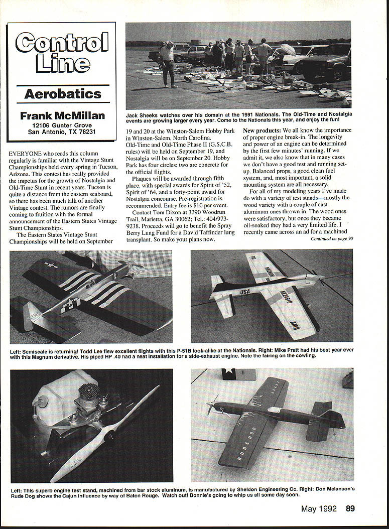
Everyone who reads this column regularly is familiar with the Vintage Stunt Championships held every spring in Tucson, Arizona. That contest has provided the impetus for the growth of Nostalgia and Old-Time Stunt in recent years. Tucson is quite a distance from the eastern seaboard, so there has been much talk of another Vintage contest. The rumors are finally coming to fruition with the formal announcement of the Eastern States Vintage Stunt Championships.
- Date: September 19–20
- Location: Winston-Salem Hobby Park, Winston-Salem, North Carolina
- Events: Old-Time and Old-Time Phase II (G.S.C.B. rules) on September 19; Nostalgia on September 20
- Facilities: Hobby Park has four circles; two are concrete for the official flights
- Awards: Plaques through fifth place, with special awards for Spirit of '52, Spirit of '64, and a forty-point award for Nostalgia concourse
- Entry fee: $10 per event (pre-registration recommended)
- Contact: Tom Dixon, 3390 Woodrun Trail, Marietta, GA 30062; Tel.: 404/973-9238
- Proceeds: Benefit the Spray Berry Lung Fund for a David Taffinder lung transplant
Make your plans now.
New products: Test stand review
We all know the importance of proper engine break-in. The longevity and power of an engine can be determined by the first few minutes' running. Balanced props, a clean fuel system, and, most important, a solid mounting system are all necessary. In many cases we don't have a good test and running setup.
Over the years I've used a variety of test stands—mostly wood, with a couple of cast-aluminum ones. The wood stands were satisfactory but had a limited life once oil-soaked. I recently ordered a machined aluminum mount advertised in the Model Engine Collectors newsletter. It arrived and was exactly what I envisioned.
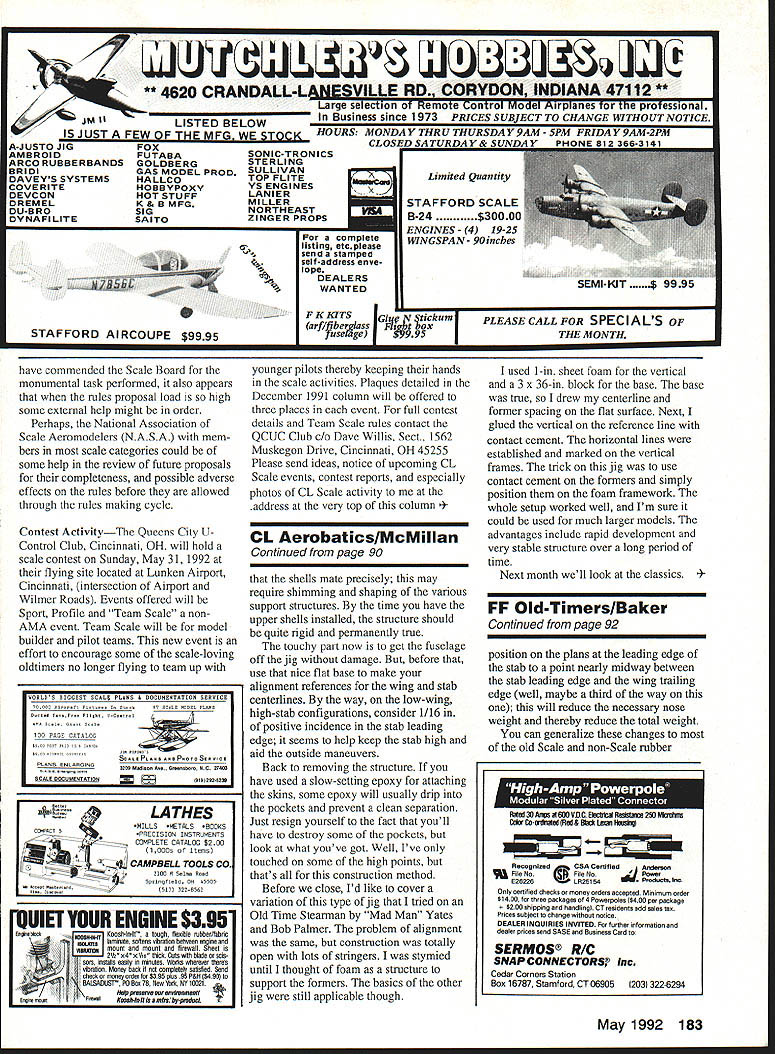
The test stand is all-metal, bar-stock construction. Major components are milled from solid bar stock aluminum; the surface contact areas are flat and parallel, and the stand has a solid feel throughout. Because the surfaces are flat and parallel, when your engine is clamped in the stand no torque is applied to the case through uneven pressure. During test running there will be no distortion that could damage the crankshaft, precision bearings, or critical sealing areas.
A unique shock mounting for fuel tanks eliminates vibration-induced fuel foaming, which can cause erratic needle settings and lean runs. Various sizes and shapes of fuel tanks are easily accommodated.
The "Pro" design is somewhat larger than previous designs and can securely mount engines up to 18 cu. in., yet it can still handle the Tee Dee .049. The large base provides additional clearance to accommodate rear-mounted components. This precision unit is a lifetime investment; I thoroughly recommend it.
Contact: Bruce Sheldon, Sheldon Engineering Co., 295 Jay Street, Birchwood, MN 55110. Price: $30, plus $4 postage and handling.
Plans: USA-11 and 1959 Nationals re-creations
Many of you will remember that last year Warren Tiahrt produced a fine set of drawings of Bill Werwag's 1959 Nationals winner. Those drawings were traced from the originals and verified against the actual aircraft. Those plans are still available, and Warren has again performed a great service by capturing the famous USA-11. The plane has been a World Champion and Nationals Champion and deserves to be flown again. With an ST .46, it really was a devastating design.
Contact: Warren Tiahrt, 7647 Twilight Court, Clarkston, MI 48016; Tel.: 313/625-5655.
Fuselage jig construction
For too many years I built airplanes by eye. Some flew well, some didn't. With the coming of the Martin Baker series it became obvious that the time invested in careful construction pays off. Since I began using some type of jig for the fuselage (and for other structures), all of my planes have been good.
Below are jig types and methods that should cover semiscale construction. I'll address other, more classic types next time.
Assume the fuselage is a sleeve shape rather than boxy. The primary consideration is to position the formers on both the horizontal and vertical centerlines. The general fuselage shape and construction methods will dictate how you set up the jig. A molded-shell type (such as the Rabe WWII fighters with deep fuselages) can be supported from the bomb bay; a stringer type (as in a recreated Stearman) may require a different approach.
WWII-style (molded shell) jig
- Start with a flat base as a reference. Assure the base is dead flat, then draw a reference centerline.
- Determine how far you will suspend the formers in the proper location; this depends on the pocket that holds the former and the proper fit.
- Draw an accurate side view of the fuselage and develop relationships from the drawing to design pockets and framework.
- Set the pockets so they hold the formers in correct spacing and in horizontal/vertical alignment—this is critical.
- Install the interior structure and all longitudinal members. Since pockets hold the formers from the bottom, plan to lift the framework out vertically.
- For Rabe-type planes, 3/32" model-balsa shells drop over the base to form the fuselage. Some shrinking and shaping of support structures may be required so the shells mate precisely. By the time the upper shells are installed, the structure should be quite rigid and permanently true.
- Use the flat base to make alignment references for the wing and stab centerlines. For low-wing, high-stab configurations consider 1/16" of positive incidence in the stab leading edge; it seems to help keep the stab high and aids outside maneuvers.
Removing the fuselage from the jig is the touchy part. If you used slow-setting epoxy for attaching skins, epoxy will usually drip into the pockets and prevent a clean separation. Expect to destroy some pockets when separating the structure—plan for that.
I've only touched on the high points of this construction method.
Foam jig variation
A variation I used on an Old Time Stearman (Mad Man Yates and Bob Palmer design) solved alignment problems for an open construction with many stringers. I used foam as the structure to support the formers.
- Materials: 1-inch sheet foam for the vertical and a 3 x 36-inch block for the base.
- Method: Draw the centerline and former spacing on the flat base. Glue the vertical on the reference line aft with contact cement. Establish and mark horizontal lines on the vertical frames. Use contact cement on the formers and position them on the foam framework.
- Advantages: Rapid development, very stable structure over a long period, and adaptable to larger models.
Next month we'll look at the classics.
Transcribed from original scans by AI. Minor OCR errors may remain.

