
Control Line: Aerobatics
Frank McMillan 12106 Gunter Grove San Antonio, TX 78231
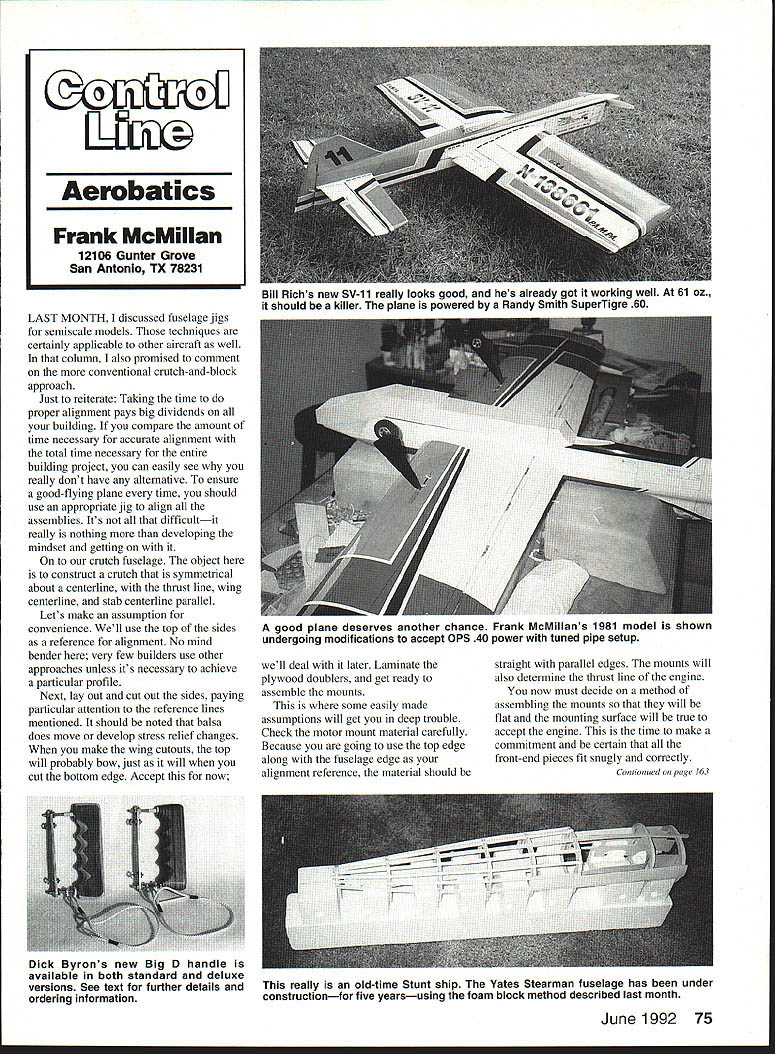
Fuselage crutch and alignment
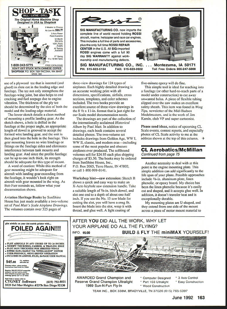
Last month I discussed fuselage jigs for semi-scale models. Those techniques are certainly applicable to other aircraft as well. In that column I also promised to comment on the more conventional crutch-and-block approach.
Just to reiterate: taking the time to do proper alignment pays big dividends on all your building. If you compare the amount of time necessary for accurate alignment with the total time necessary for the entire building project, you can easily see why you really don't have any alternative. To ensure a good-flying plane every time, you should use an appropriate jig to align all the assemblies. It's not that difficult — it really is nothing more than developing the mindset and getting on with it.
On to our crutch fuselage. The object here is to construct a crutch that is symmetrical about a centerline, with the thrust line, wing centerline, and stab centerline parallel.
Let's make an assumption for convenience: we'll use the top of the sides as a reference for alignment. No mind-bender here; very few builders use other approaches unless it's necessary to achieve a particular profile.
Next, lay out and cut out the sides, paying particular attention to the reference lines mentioned. It should be noted that balsa does move or develop stress-relief changes. When you make the wing cutouts, the top will probably bow, just as it will when you cut the bottom edge. Accept this for now; we'll deal with it later. Laminate the plywood doublers, and get ready to assemble the mounts.
This is where some easily made assumptions will get you in deep trouble. Check the motor mount material carefully. Because you are going to use the top edge along with the fuselage edge as your alignment reference, the material should be straight with parallel edges. The mounts will also determine the thrust line of the engine.
You now must decide on a method of assembling the mounts so that they will be flat and the mounting surface will be true to accept the engine. This is the time to make a commitment and be certain that all the front-end pieces fit snugly and correctly.
Motor mounts and mounting plate
Another necessity to deal with at this point is the engine mounting plate. This simple addition can add significantly to the life span of your plane. Possible materials include 1/8-in. aluminum plate, phenolic, or epoxy board. My choice has been linen phenolic because it's easily cut and shaped, accepts glue well, doesn't transfer heat, and is exceptionally durable.
My mounting plates are U-shaped and extend from one side of the mount across a piece of motor mount material to the other side. The mounting plates are centered on and glued to the firewall. I then install nylon locknuts that have been epoxied into place from the back. The engine is then bolted to the mounting plate. Use a 5-minute epoxy to fillet and help secure the assembly. A light bead of epoxy fillet on the back side will help relieve stress. If you have any concerns about alignment, place the engine on the mount and check everything with a long straightedge before final drilling and bolting.
Another problem is vibration. Possible solutions include:
- use rubber isolators between the engine and the mount;
- use an engine mounting bolt with a spring washer to isolate vibration;
- use thin rubber sheet between the mount and firewall;
- bolt the mount directly and rely on the engine's own rubberized mounts.
After drilling the mounting holes, assemble the plate and mounts with slow-setting epoxy and bolt on the engine to permanently align the system. You should also bridge the gap between the mounts aft of the main firewall with cross-grained 1/2-in. balsa. This will help maintain true alignment and rigidity.
Cowl
A simple cowl can be made using a 1/16-in. plywood doubler ring and balsa sheeting. Cut the ring to the outside dimension of the firewall, then glass the inside with a layer of cloth and epoxy to keep it from splitting. The balsa can be hot-wired or cut and shaped to fit and can be filleted to the ring with five-minute epoxy.
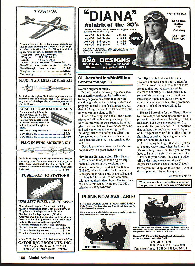
Fuselage assembly and alignment
Next, glue the fuselage sides with doublers to the mount crutch. Do this on a long, flat surface with the crutch flat and the sides upright.
Now we must establish alignment and a proper taper/shape. First, lay out the reference points on your table. In the case of a straight taper on the sides from the wing leading edge to the rear of the fuselage, these reference points can be limited to the centerline, firewall, and moment locations, but that is a minimum. Then affix the basic fuselage to the work surface and start installing the formers.
To digress a little, my building surface is 1/4-in. plate glass with the alignment layout marked on sheet cork under the glass. The plate glass is shimmed flat with playing cards prior to final alignment. I tack-glue the components to the glass to hold them in place.
Once the sides are glued to the surface in alignment, start adding your formers. Make sure the formers are square to the building surface. You might consider using angled formers front-to-back to get a geodetic effect. I don't use this method; instead I use crossed 1/8 x 1/4-in. inserts between the formers, top and bottom. The strips are in tension, so soft, light wood is perfectly acceptable. In any case, keep the sides vertical with right-angle templates while you install the formers.
In the case of a fuselage with a slightly altered top-view profile, align the assembly by adding a 1/8-in. sheet balsa plate between the fuselage sides from the leading edge of the wing to the rear. This sheet has the shape that you want the sides to take. Tack the sheet to the building surface aligned as noted above, and continue as in the previous approach.
Build the basic fuselage all the way up through the cross stringers, including the entire nose section. All you need to do now is pop the fuselage off the glass with a long blade. The structure will be straight and rigid. That is, it will be straight and rigid until you cut out the pieces from the bottom in order to install the wing. Now that nice, straight top reference becomes a bit wobbly.
Before you put the wing in the fuselage, recheck all your alignment lines: centerline, wing trailing edge line, and stab trailing edge line. Position the fuselage over the centerline with the cutouts for the wing and stab in the appropriate locations. Recheck the alignment, and tack-glue the fuselage in place. Drop the wing in and check the fit. When it's right, position the trailing edge over the alignment marks.
Before you glue the wing in place, check the centerline marks on the leading and trailing edges to be certain that they are equal height above the building surface and properly located in the fuselage crutch. All that checking sounds like a lot of effort, but do you want the plane to fly?
Glue in the wing, and add all the bottom pieces and all the bracing you can get to it now. Before you lift the structure from the glass, confirm that you have secured the centerline and stab centerline marks using the flat building surface as a reference. Since the fuselage top was flat on the surface when you glued the wing in, it has remained flat and true.
Get this procedure down, and you're well on your way to a great-flying plane.
New items
Got a note from Dick Byron, of Scale-team fame, announcing his Big D handle. It comes in two versions:
- standard version: $18.95
- deluxe (solid walnut): $23.95
Line spacing is adjustable, as are offset and line length. The handle comes complete with the required safety thong. Contact Dick at 2310 Citrus Lane, Arlington, TX 76014; telephone: (817) 461-7705.
Tech tip — fillets and finish
I've talked about fillets in previous columns, and if you've tried for that "front row" finish before, the chances are good that you've experienced the infamous bubbling. Bill Rich shared some of his recent experiences with his latest super finish and was trying to reflect on what caused his pitting problems. After all, he had done everything he usually does.
He used Epoxikote for the fillets, followed by nitrate dope for bonding and gray auto primer for smoothing and building the fillet. Basically, I use the same procedure. So, where did the problem occur? Bill theorized that perhaps the trouble was caused by oil on his fingers when he felt the fillets during finishing, or perhaps by using too much paint on some of the coats.
Actually, my feeling is that he's right on all counts. Many times when the fillets lift it's something minor that fails you. So you have to be very careful:
- Never touch the fillets with your hands. Use tissue to wipe off the dust, and clean carefully with degreaser between coats of dope.
- Don't let the paint build up too thick.
- Avoid the temptation to lay on heavy coats.
PAMPA news
Finally, congratulations to Phil Granderson on assuming responsibility for editing the PAMPA newsletter. Great job on your first issue! Join us in PAMPA; contact Tom Morris at 1019 Creek Trail, Anniston, AL 36206.
Transcribed from original scans by AI. Minor OCR errors may remain.

