
CONTROL LINE AEROBATICS
Frank McMillan, 12106 Gunter Grove, San Antonio, TX 78231
In the last column I discussed some state-of-the-art advances in Precision Aerobatics models, looking at later construction techniques of built-up structures, such as the Lost Foam method. The object, of course, is to build precise, true structures.
As the concept matured, options other than merely duplicating standard construction patterns became available. Now it is possible to correctly assemble accurate geodetic wings the first time, every time. This gives such added benefits as the stiffness inherent in the geodetic approach, but it also allows a reduction in the structure's parts count and therefore the weight, which is what we are really after.
A critical point here is that there are several assumptions that necessarily go along with driving toward the ever-elusive light-weight goal. Practically speaking, it doesn't do you any good if your 45-ounce piped model flexes in anything but dead air; its controls wash out and there are cracks after the first few flights.
The structure must be rigid, maintain the accuracy built into it under sustained heavy flight loads, and be durable — capital D. When these tenets are compromised, you're in trouble. The best example of this goes back to the Nationals held in Reno, Nevada. Many top competitors were concerned about the altitude and the heat. There were quite a few lightweight models, but most were left in cars because they were just too flexible. The older, heavier (but more rigid) models were flown — a bit faster — and did reasonably well.
Any discussion regarding light weight must deal with the use of composite materials. Many forms of carbon fiber have been extremely effective in reinforcing structures. Except for a few stunt models, however, I have doubts that its potential has been reached.
Many have used strips of .007 or .014 x .250 inch to reinforce structures that probably didn't require it. In general, the design of most current structures has followed traditional techniques, but these techniques were not developed using composite technology.
Paul Walker's work with carbon main spars in an I-beam configuration is one direction I foresee construction technology going. But there is always a kicker: just as there is an up-front time investment to make a jig, there is an up-front time investment to make a composite structure (visualize a one-piece wing spar), construct the mold, then lay up the structure in epoxy and carbon. It makes me tired just thinking about it!
Cataloging what's required to infuse this type of technology brings up the question, "Is it worth it?" The process requires lengthy, highly accurate work. If you haven't settled on a specific design, this could certainly generate a lot of repetitious effort. But where there is a proven design, the time can be amortized over many models. There is possibly a commercial application for designs such as the Pattern Master, SV12 series, etc.
So far, I've been thinking about interior structure components. The next logical step is major components: wings, stabs, and fuselages. In the RC community there have been many successful fiberglass fuselages, some with carbon reinforcement, and some designed with take-apart sections.
The FAI Team Race community, especially the Russians, have done major work in carbon fuselages (in very limited production). I viewed examples in both T/R and FAI Speed at the '93 Nationals, and they were spectacular. This showed me that it can be done; it's only a matter of size.
In addition, newer, lighter forms of carbon are becoming available from Russia. This is not just the lightweight mat, which is available down to 0.25 ounce per square yard; the woven material necessary for the proper strength is also becoming available at reasonable prices.
I'm sure that working with carbon will be somewhat different than fiberglass, but it is certainly manageable. Again, this is a major project because of the molds and the investment for the materials. But I see this as a viable option to save weight and improve durability. I sure would want to know the design before proceeding!
The flying surfaces are another story. Sailplane competitors commonly use glass-skinned wings fabricated by the vacuum-bag method. These are superb, and the systems to apply the skins are readily available at reasonable prices.
Because the wing types are so different, this is not what I had in mind. The stunt wing has much more volume, and perhaps an approach other than skinning foam may have to be used.
Some years ago Al Rabe devised an approach to working up a semiscale MK 22 Spitfire. It was an elegant design, much in the style of his famous Mustangs and Bearcats. The concept in molding was to drive the total time investment in making a semiscale stunter down from approximately 800 hours (yes, that's accurate!) to 100–150 hours.
The idea was to detail the molds with all of the blisters, scoops, panel lines, etc., and lay up the skins on the top of the base color. When the plane was assembled, only trim and insignia needed to be applied.
Back to the wing design — his design involved three major moldings. A main section was the entire leading edge from the high point on top, wrapping around the leading edge to the bottom at the high point. This section contained the full shape of the wing, including the dihedral. It becomes the building block to assemble the interior structure and the remaining carbon sections.
Think of the wing as a true monocoque structure. Some substructure to mount components such as landing gear, retracting gears, controls, etc., will be required. A full-span, full-depth main spar with wide caps would be installed. This is used to support the bonding of a top rear section and bottom rear section, which completes the structure. Several ribs to support the outer structure would be necessary.
The concept sounds great, but it hasn't been done yet. A leading-edge mold was developed, but at the time (early '80s) the lightweight carbon cloth was not available at a reasonable cost.
As to the tail surfaces, I have doubts that a molded surface can be made as light as some of the new geodetic structures. Certainly, reinforcement with carbon strips is a proven method to increase strength and decrease the structure, thereby saving weight.
Having just finished several open-bay geodetic stabs, I recommend you give those a try. I did not believe how strong they would be until I built my own. Use a flat stab rather than an airfoil, since they seem to track better and are much easier for many builders to align properly.
To pull this together by predicting where we are going: I don't see the major components being molded in carbon in the near future. But I do see more use of molded major substructures for wing and stab spars. This won't be a technological jump, but more of an evolutionary step. If and when the semi-scales are tried again, perhaps the fully molded composite stunter will surface.
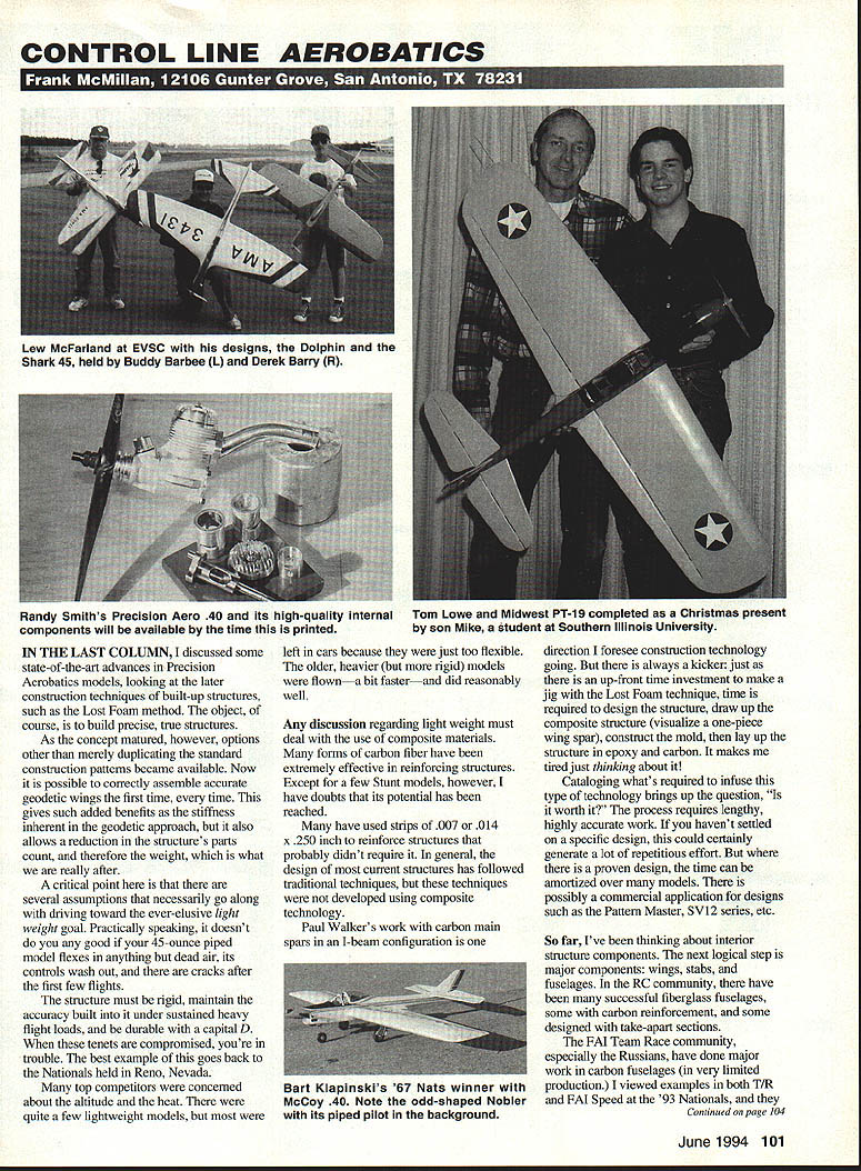
New Product: Aero Products
Aero Products (1880 Scenic Highway, Snellville, GA 30278) announces a new series of control-line stunt engines: the Precision Aero .40. This engine is designed and manufactured by Randy Smith and Henry Nelson and is designed specifically for CL aerobatics, from the inside out.
Features:
- Mildly timed AAC piston and liner
- Dual high-speed rear bearings
- True venturi
- Available in four different versions: side or rear exhaust, with timing for pipe or standard configurations
- Each engine hand-assembled and blueprinted
- Weight: slightly more than ten ounces
Contact:
- Randy Smith, Aero Products, 1880 Scenic Highway, Snellville, GA 30278
- Telephone: (404) 979-2035
- Fax: (404) 985-5085
Transcribed from original scans by AI. Minor OCR errors may remain.

