
CONTROL LINE AEROBATICS
Frank McMillan
12106 Gunter Grove, San Antonio, TX 78231
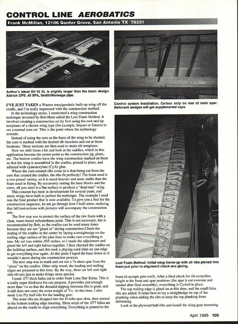
I've just taken a Warren truss / geodetic built-up wing off the cradle, and I'm really impressed with the construction method.
In the technology series I mentioned a wing construction technique invented by Bob Hunt called the Lost Foam Method. It begins by using the root and tip templates of a chosen wing type (for example, Impact or Saturn) to cut a normal core set. This is where the technology extends.
Instead of using the core as the basis of the wing to be sheeted, the core is marked with the desired rib locations and cut at those locations. These sections are then used to make rib templates.
The saddles become the centerpoint as the construction jig and plans. The bottom cradles have the wing construction marked on them so the wing is assembled in the cradles, pinned in place, and adhered with cyanoacrylate (CyA) glue. Because the ribs are cut from the same core that created the cradles, the ribs fit perfectly.
The foam used for the cradles is a two-pound variety, heavier and more stable than the foam used in flying models. By accurately cutting the base blocks and the cores, all you need is a flat surface to produce a "dead true" wing.
This concept has been developed for several years, and many wings have been built to perfect the technique. The example I used was the final product now available. Below is a feel for the construction sequence; full instructions with pictures accompany the construction sets.
Building sequence
- Protect the raw foam surface with a clear, water-based polyurethane paint. This is not strictly necessary but is recommended so the cradles can be reused without being glued to.
- Check the mating of the cradles in the center by laying a straightedge on the trailing-edge plan lines to ensure everything is true. Make any small adjustments, then glue the left and right halves together.
- Check the cradles on the building surface. Use a shim if necessary to make the assembly true. Tape the base down so it won't move during construction.
- Mark and cut out a 1/8" sheet spar from the plans on the cradles. Prepare other strip wood and the leading and trailing edges at this time. Note there are left and right side rib sets for added precision.
- Use 0.077"-thick balsa cut to order (I used Lone Star Balsa). This thickness provides slightly more than 1/16" and eliminates dipping between ribs without the extra weight of 3/32".
- Make Lite Ply half-ribs for the landing gear bays.
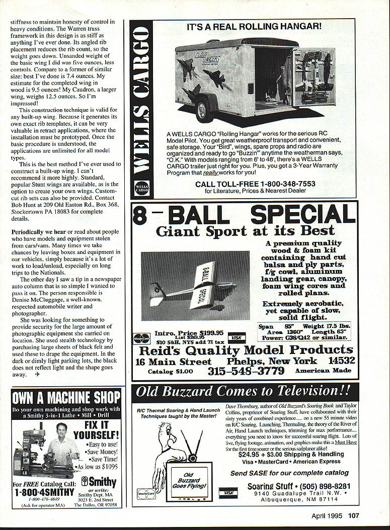
- Drop the main ribs into the D-tube spar slots, then pin them to the bottom trailing-edge sheeting. Place shim strips of the 0.077" balsa on the cradle to align everything. The foam accepts pins well.
- After a final check for rib centerline height at the front and spar positions (the spar is cut oversize and sanded after final assembly), CyA the ribs in place.
- Glue on the top trailing edge and add small false ribs. Lay a straightedge on top of the planking when adding the ribs to keep the top planking from deforming.
- Install the plywood half-ribs and the wing gear mounting system.
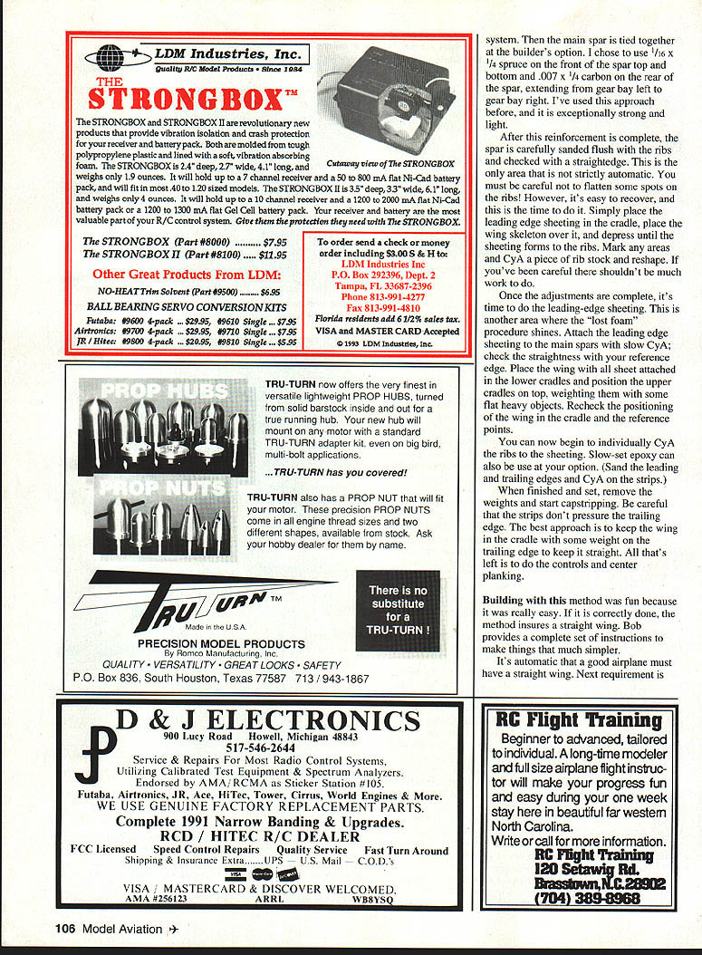
- Tie the main spar together as desired. I used 1/16" x 1/4" spruce on the front of the spar (top and bottom) and 0.007" x 1/4" carbon on the rear of the spar, extending from gear bay left to gear bay right. This is exceptionally strong and light.
- Sand the spar flush with the ribs and check with a straightedge. Take care not to flatten any rib spots—this is the time to correct them. If necessary, glue in rib stock pieces and reshape.
- Attach the leading-edge sheeting to the main spars with slow CyA; check straightness with your reference edge. Place the wing with all sheeting attached in the lower cradles, position the upper cradles on top, and weight them with flat heavy objects. Recheck positioning and reference points.
- Individually CyA the ribs to the sheeting. Slow-set epoxy can also be used if preferred. Sand the leading and trailing edges and CyA on the strips.
- When set, remove the weights and start sanding and fairing the sheeting. Keep the wing in the cradle with some weight on the trailing edge to keep it straight while working.
- Complete the controls and center planking.
Building with this method was fun because it was easy and, if done correctly, it assures a straight wing. Bob provides a complete set of instructions to make things even simpler.
Spar reinforcement and adjustments
The Warren truss framework in this design is very stiff. Its angled rib placement reduces the rib count and therefore lowers weight. The unsanded weight of the basic wing I built was five ounces, less controls. Compare that to a previous wing of similar size at 7.4 ounces, and my estimate for a completed wing in wood is about 9.5 ounces. My Caudron, a larger wing, weighs 12.5 ounces. So I'm impressed.
This construction technique is valid for any built-up wing. Because it generates its own exact rib templates, it can be especially valuable in retract applications where the installation must be prototyped. Once the basic procedure is understood, the applications are unlimited for all model types.
This is the best method I've used to construct a built-up wing. I can't recommend it more highly.
Ordering and contact
Standard, popular stunt wings are available, as is the option to create your own wings. Custom-cut rib sets can also be provided. Contact Bob Hunt at:
Bob Hunt 209 Old Easton Rd., Box 368 Stockertown, PA 18083
Security tip: protecting equipment in vehicles
Periodically we hear about models and equipment stolen from cars and vans. Many of us take chances by leaving boxes and gear in vehicles because it's a lot of work to load and unload, especially on long trips to the Nationals.
A simple tip I picked up from automobile writer and photographer Denise McCluggage: use large sheets of black felt to drape over your equipment. In dark or dimly lit parking lots the black felt doesn't reflect light and the outline of the gear is much less obvious.
Transcribed from original scans by AI. Minor OCR errors may remain.

