
CONTROL LINE AEROBATICS
Frank McMillan, 12106 Gunter Grove, San Antonio TX 78231
Flying Tips:
It's been said that "there's nothing new under the sun," so this hint has probably been related somewhere before.
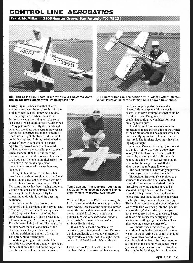
The story started when I was at the Nationals (Nats) site trying to make some sense out of what could loosely be described as "my pattern." Generally the rounds and squares were okay, but a certain preciseness was missing, particularly in the "bottoms." There was a slight climb or overturn that I couldn't suppress. Nothing I tried, whether center of gravity adjustment or handle adjustment, proved very effective until I decided to check the propeller pitch to see if it had changed. It hadn't, but for some reason not related to the bottoms, I decided to go down an increment on pitch (from 4.0 to 3.9 inches); that small adjustment immediately produced the easy bottoms, "locked in."
I forgot about this after the Nats, but it resurfaced at a flying session with my friend John Hill, an excellent flier who's working hard for his return to competition in 1998. For some time we had been having problems working out consistent bottoms for John. We thought that his being a lefty had something to do with it, and the guessing continued.
At the end of this last session, he remarked that his airplane didn't lay in the line like mine. (He'd recently flown my Nats model.) By coincidence, one of my Nats props was pitched at 3.9 and his was at 4.0. (He was running a PA-51, so the prop was a 12-inch three-blade.) Almost like magic, the bottoms were there as were many of the characteristics of my airplane, such as tracking, positioning, and turn. It was the same prop, but different pitch.
Without getting technical (which is probably way beyond me anyhow), the heart of the situation is the load on the engine and how the increased load causes it to react. With the 4.0 pitch, the PA-51 was sensing the increased load from the control deflections and producing more power. Because of the additional power and/or the time and duration of the additional power, an additional hop or climb was produced. This is very subtle and wouldn't necessarily be recognized as a distinct problem. But it is there!
If you experience the problems I've described, you might give this a try; I'm sure that it is applicable to most power setups. It might work even better with the higher-pitch conventional 2-4-2 breaks. It's worth a try.
Construction Tips:
I can't count the number of times I've stressed that accuracy is critical to good performance and an "honest"-flying airplane. Most steps in construction have assumptions that could be reevaluated, and I'm going to discuss a couple that could give you ideas for your building techniques.
A widely used fuselage-construction procedure is to use the top edge of the crutch as the prime reference line against which the thrust and flying surface reference lines are measured. The fuselage sides must have the top edge straight.
You've cut and sanded that edge (both sides) so that it's right on, so you're done there. Wrong! The best you can assume is that it was straight when you did it. If the air is humid, the edge will move. Sitting around waiting for the wing to be installed will allow the prime reference line to bow.
The next question is, how do you provide for this in your construction procedure? Throughout the years I've evolved to a sequence that uses the final assembly to return the fuselage to the desired straight line. Since the wing is accessed through cutouts on the bottom, normally this process of cutting the sides relieves the stress and the assembled crutch can be glued to your assembly surface/jig. This will get back the good reference. Drop the wing pocket into the jig/table surface, which you have leveled. Measure. Spend the time necessary aligning leading and trailing-edge centerlines. It gives you the correct settings (0).
You should check this root to tip. The wing should lay in the fuselage, of its own weight, at these settings so as not to induce any stress. This procedure may take considerable time, but it is the most important alignment in the assembly sequence. When you insert the pieces you removed to place the wing in the fuselage, this will lock the wing in with the fuselage top and the wing centerline leveled to the table.
Another area aligned by this procedure is the engine mount. Actually, a great part of this setup is developed in the crutch construction and takes place before the previous assembly procedure. I've evolved to cutting the engine mounts, firewall sections, and mounting plates, then assembling them on a piece of thick plate glass to assure flatness; this is where the "package" can take on some errors.
When I cut my engine mounts from 1/8" x 3/8" maple stock, I start with dead-true pieces carefully selected to ensure that I have some tank-adjustment capability. After I notch the rear of the mounts aft of the engine 1/8", I check the height along the cut with a dial caliper and sand it true and level. I assemble the mounts on the plate glass with the firewalls and 3/8" balsa cross-grain.
This structure is then glued to another plate of 1/8" Lite Ply or 1/8" balsa, which bridges the entire mount structure on top, front to back. Since I've had another opportunity to induce errors, I check it again with dial calipers and sand it level on the engine/crutch surfaces. The true crutch now rests on the top surface, which was used as a reference. (Any errors were taken out by making the other surfaces equal and parallel.)
The engine mounting plate is now epoxied to the mounts, with the engine itself used as a clamp to ensure a solid mount. With everything level, the fuselage sides (with doublers in place) are epoxied to the engine crutch.
As you have followed these two setups you might be wondering, "why take so much care and trouble?" By getting into this sequence you prevent additive tolerance, creating thrustline offsets and unwanted incidence in the wing/tail.
Remember that it doesn't take much to make a potentially great airplane ordinary. Have you ever measured with a dial caliper or micrometer different plywood/balsa sheets side-to-side, end-for-end? They can vary, producing unknown settings, however small. It pays to check!
New Items:
I've reviewed a video by Bill Harding titled Instruction to Control Line. This is the best tape I've seen on basic control line flying. The subject matter is basic, starting with the construction of a .12 Sig Skytray and proceeding to the required steps to get it safely into the air. Then the video progresses to construction of the built-up wing, .35-size version.
Bill Harding does broadcast videos for a living, and the tape shows it. It is high quality and has all the latest video technical features, but above all, it does what it was intended to do—get a beginner into the air. If you need classroom work for sport, school, or club programs, this is a must! Contact Harding Aero Products, 4782 Unity Lane Rd., New Waterford OH 44445; Tel. and Fax: (330) 457-1600.
Bill has also released the Brodak Control Line Fly, which features a talk by George Aldrich about model engines. Tapes are $19.95 plus $3 shipping and handling. Ohio residents add $1.20 sales tax.
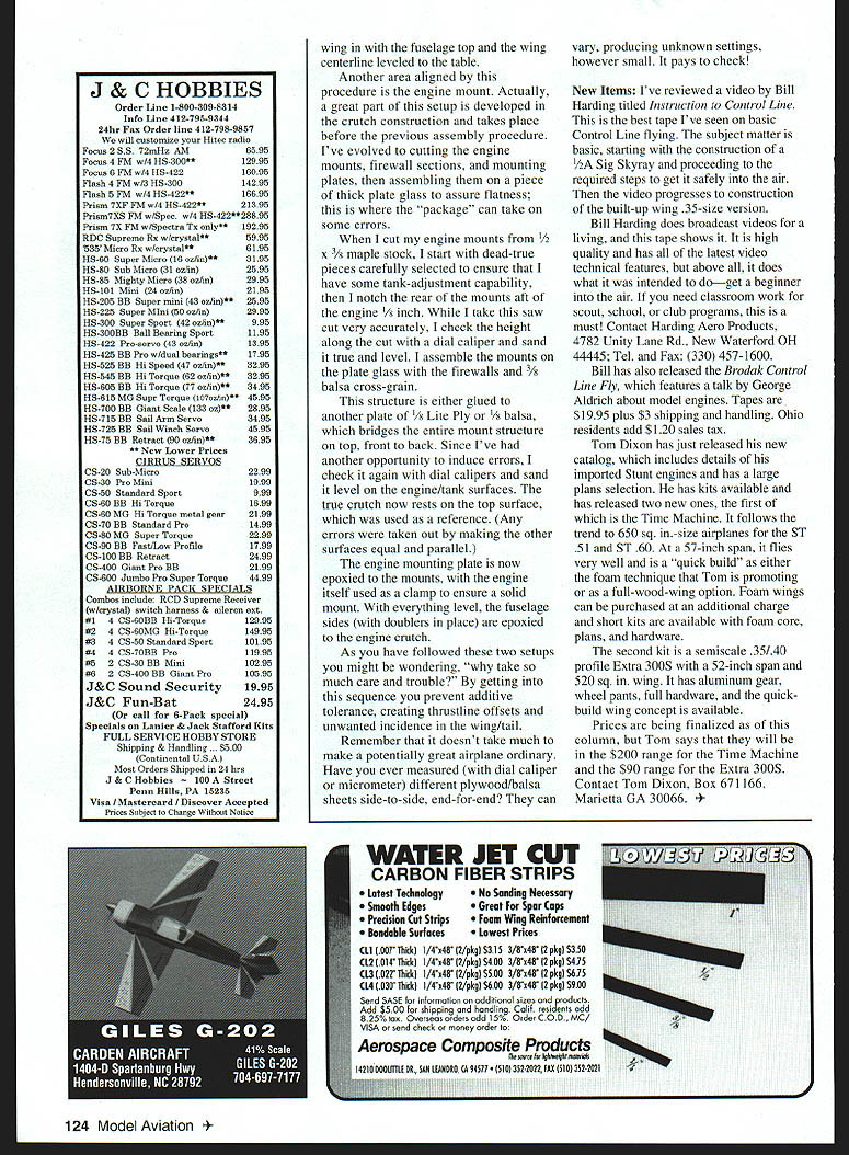
Tom Dixon has just released his new catalog, which includes details of his imported ST engines and has a large parts selection. He also has kits available and has released two new ones, the first of which is the Time Machine. It follows the trend to 650 sq. in. size airplanes for the ST and .51 and .60. At a 5-inch span, it flies very well and is a "quick build" as either a foam fuselage or a built-up fuselage kit. Tom is promoting it as a full-wing option. Foam wing sections can be purchased at an additional charge and short kits are available with foam core, plans, and hardware.
The second kit is a semiscale .35/.40 profile Extra 300S with a 52-inch span and 250 sq. in. wing. It has aluminum gear with wheel pants, full hardware, and the quick-build wing concept is available.
Prices were being finalized as of this column, but Tom said they would be in the $200 range for the Time Machine and the $90 range for the Extra 300S. Contact Tom Dixon, Box 671166, Marietta GA 30066.
Transcribed from original scans by AI. Minor OCR errors may remain.

