
CONTROL LINE AEROBATICS
Frank McMillan 12106 Gunter Grove, San Antonio TX 78231
Vertical center of gravity
I haven't written about trimming in a while, so I thought I'd get into a very narrow subject that can seriously affect many other trim adjustments: the vertical center of gravity (CG).
When I think CG, I usually focus on the fore-and-aft CG, which does have a big impact on flight characteristics. However, having an airplane with the vertical CG not located in line with the leadout exit will prevent you from achieving the usual first step in the trim process: leveling the wings.
What I'm considering is this: your airplane is suspended by the leadouts. If the vertical CG is displaced from the line where the extension of the leadout exit intersects the fuselage, a force is created that pulls on the fuselage. That pull attempts to force the vertical CG into line with the leadouts when the model is flying. The force working on the fuselage naturally affects the wings, so if the displacement is even a little off, the wing cannot be leveled properly.
Checking the vertical CG
As with any new airplane, it's a good idea to check the vertical CG. It's simple — you only need a way to suspend your model by the leadouts and a plumb bob. The idea is to look at how your model hangs versus a true vertical plumb line. Surprisingly, a problem will show up quite vividly.
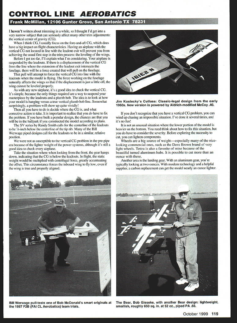
Then decide where the CG is and what corrective action to take. It is important to realize that you do have to fix the problem. If you built a popular design, the chances are you will be in the ballpark if you constructed the model according to plans. For example, the SV series by Randy Smith calls for the centerline of the leadouts to be 1/8-inch below the centerline of the tip rib. Many of the Bill Werwage piped designs call for the leadouts to be in a similar relative position.
We were not as susceptible to the vertical CG problem in the pre-pipe era because of the lighter weight of the power systems, although it's still a good idea to check every airplane.
How vertical CG affects flight
Take the situation where, when looking from the front, the gear hangs down, indicating that the CG is below the leadouts. In flight, the static weight is multiplied by centrifugal force, greatly accentuating the offset. This forces the inboard wing to fly low, even if the wing is true and properly aligned.
If you don't recognize that you have a vertical CG problem, you can wind up chasing an impossible situation. I've done it several times, and it's no fun.
The opposite circumstance—when the top of the airplane is heavy—doesn't happen very often, but it does occur. Sometimes it appears in older airplanes that have low wing centerlines relative to the thrustline. The characteristic of a top-heavy fuselage is that the inboard wing will tend to fly high when it's upright. There is the same problem in trimming it out by other means than correcting the vertical CG.
Corrective measures
You need to think about how to fix the situation, but consider the severity before deciding to cut or otherwise modify structure. Before exploring structural cuts, you can often lighten or redistribute components:
- Wheels are a big source of weight—especially many of the nice-looking commercial ones. Replacing heavy wheels with very light types (for example, Dave Brown's light wheels or Tettra wheels with turned aluminum hubs) can save more than an ounce.
- Landing gear can be heavy. An aluminum gear might weigh around two ounces; replacing it with a modern carbon gear can reduce that by nearly an ounce.
If the lower portion of the model is heavier, try lightening components first. If the top of the airplane is too heavy, adding weight low (for example, heavier wheels) can help.
Sometimes trimming requires structural changes. Repositioning leadouts or cutting a wing tip to adjust geometry/weight may be necessary if other measures don't suffice.
Example: Aldrich AG-1
Years ago I built an Aldrich AG-1 for Classic. The design has an upswept wingtip, showing the leadouts exiting from the raised centerline. I thought that since I was using adjustable leadouts, I'd bring the leadouts out from the center of the wing; after all, it was a simple design with a low wing. Did I outsmart myself?
On the AG-1's first flights, it behaved exactly as a high vertical CG should have. When I got home I hung the model by the leadouts, and sure enough, the fuselage top hung down. I cut the tip and moved the leadouts up—instant airplane. That's the same reaction most airplanes have when the vertical CG is repositioned correctly. If it's correct, you don't have problems; if it's not, you'll know it big-time.
Wind measurement
Wind is a big factor in flying, but model pilots usually guess the velocity and almost always overestimate it. Through the years I've had several devices for measuring wind, but none were satisfactory.
A couple of years ago I saw Bob Gialdini using a measuring instrument at the Vintage Stunt Championships; he said he used it when he went sailing. My wife conspired with Bob and one of his instruments materialized. I've been using it regularly for the last year and recommend it.
Speedtech Instruments handles various types of portable, self-powered electronic instruments. I use the Skywatch 3-D model SW-3. It's solar-powered and provides hands-free omnidirectional ±5% accuracy. It's reliable, trouble-free, and easy to use. There are several other types you may prefer.
Contact Speedtech for a current catalog. I've talked to the people there; they are helpful and knowledgeable about modelers' needs.
Speedtech Instruments 10413 Deerfoot Dr., Great Falls, VA 22066 Order: (800) 760-0004 Fax: (703) 759-0509 Web: http://www.speedtech.com
Transcribed from original scans by AI. Minor OCR errors may remain.

