
Control Line: AEROBATICS
Wynn Paul
The subject is control line handles. What can we stunt fliers do now that the supply of E‑Z Just has been exhausted and Bob Hunt and Gene Martine are no longer producing their handles? No manufacturer or prospective manufacturer I've talked to in the past couple of years has wanted to risk the liability lawsuits that caused the demise of E‑Z Just. So we must improvise if the Fox, Tatone, or Sullivan handles that are available do not fit our needs.
Let's examine some of the characteristics of a good handle.
By far the most popular handle has been the very inexpensive small E‑Z Just; it was a tight fit for most adult hands, but we all liked the 3‑15/16 in. line spacing. The leadout line was adjustable (on the ground) for inside/outside turning equivalence. Bob Hunt went one step further with his C.S.C. Trujust handle that allowed in‑the‑air adjustment of inside/outside turning equivalence. The Trujust has line spacing of 4‑1/4 in., mainly because the space on the handle was plenty big for most any size hand — which should have made the handle much more sensitive than the small E‑Z Just. However, the Trujust handle had considerably more "overhang" than the E‑Z Just, which tended to dampen the sensitivity of the handle (we will examine "overhang" below).
Recently, Hunt said that he designed the handle to fit his hand. He used the long overhang to slow down the action of the handle and to make use of the wrist action that he feels is one of the characteristics of his flying. He said that this setup allowed him to fly with more nose weight in the airplane, which would make for a better‑grooving airplane.
Overhang: definition and discussion
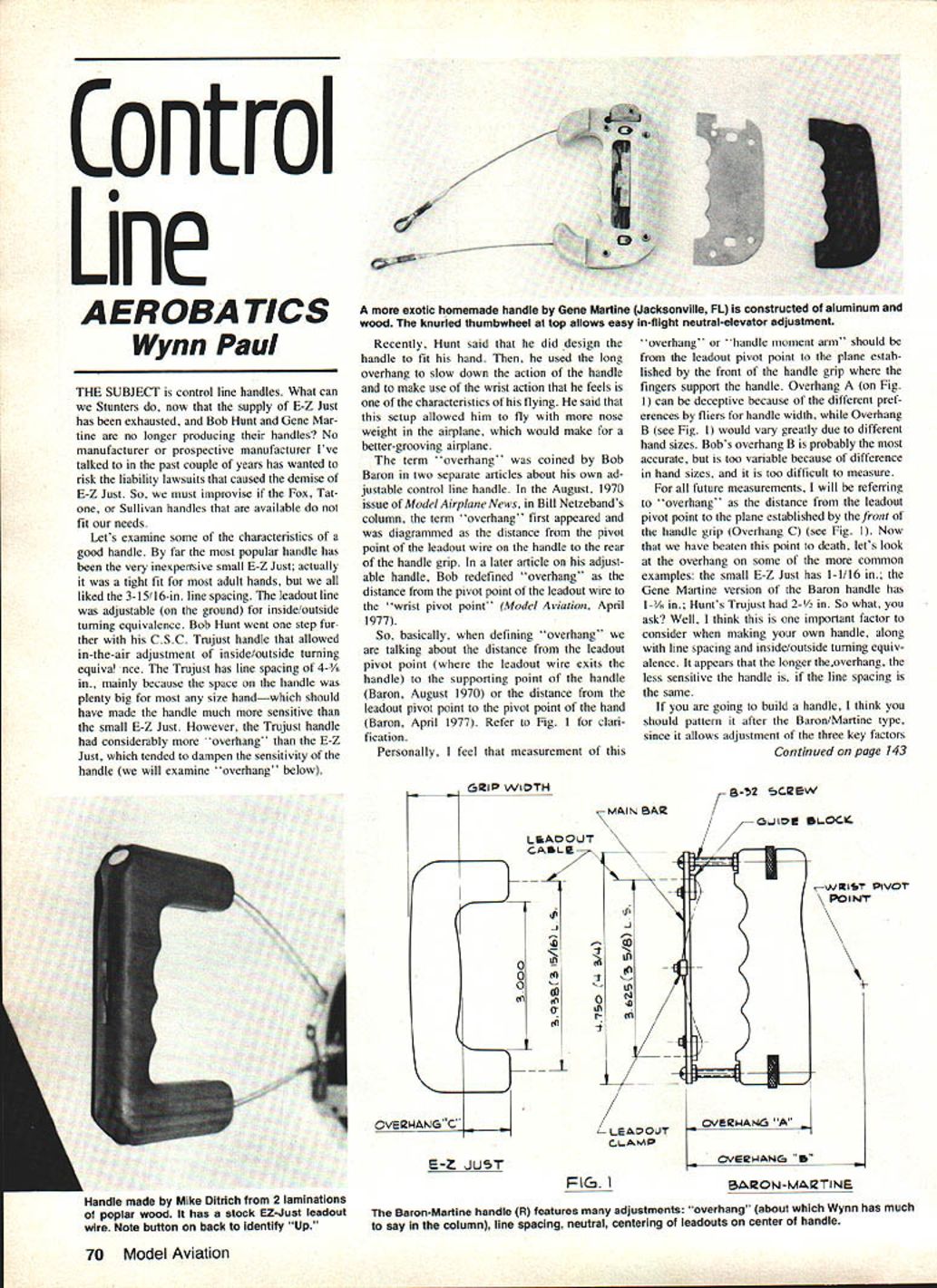
The term "overhang" was coined by Bob Baron in two separate articles about his own adjustable control line handle. In the August 1970 issue of Model Airplane News (Bill Netzeband's column), the term "overhang" first appeared and was diagrammed as the distance from the pivot point of the leadout wire on the handle to the rear of the handle grip. In a later article on his adjustable handle, Bob redefined "overhang" as the distance from the pivot point of the leadout wire to the "wrist pivot point" (Model Aviation, April 1977).
So, when defining "overhang" we are talking about the distance from the leadout pivot point (where the leadout wire exits the handle) to the supporting point of the handle (Baron, August 1970), or the distance from the leadout pivot point to the pivot point of the hand (Baron, April 1977). Refer to Fig. 1 for clarification.
Personally, I feel that measurement of this "overhang" or "handle moment arm" should be from the leadout pivot point to the plane established by the front of the handle grip where the fingers support the handle. Overhang A (on Fig. 1) can be deceptive because of different preferences by fliers for handle width, while Overhang B would vary greatly due to different hand sizes. Bob's Overhang B is probably the most accurate, but is too variable because of differences in hand sizes and is too difficult to measure.
For all future measurements, I will refer to "overhang" as the distance from the leadout pivot point to the plane established by the front of the handle grip (Overhang C) (see Fig. 1). Now that we have beaten this point to death, let's look at the overhang on some of the more common examples: the small E‑Z Just has 1‑1/16 in.; the Gene Martine version of the Baron handle has 1‑3/16 in.; Hunt's Trujust had 2‑1/2 in. What this means is that overhang is an important factor to consider when making your own handle, along with line spacing and inside/outside turning equivalence. It appears that the longer the overhang, the less sensitive the handle is, if the line spacing is the same.
If you are going to build a handle, I think you should pattern it after the Baron/Martine type, since it allows adjustment of the three key factors.
Adjustable line spacing and trim
Hunt pointed out another ideal feature of the Baron/Martine handle: the entire handle line spacing can be moved up or down relative to the pivot point of the wrist — which can substantially alter the trim of the airplane without having to handicap performance by adding trim weight to the plane. For instance, moving the down‑line UP (towards the pivot point of the wrist) will decrease the amount of outside turn, which can solve the problem of a plane that turns faster outside than inside. Or both lines can be moved up or down the same amount to give a different "feel" to the handle.
However, the handles that Gene Martine produced had a maximum line spacing of only 3‑3/8 in., and the stock overhang was greater than the small E‑Z Just handle (1‑3/16 in. for the Martine, 1‑1/16 in. for the E‑Z Just), which I found much too slow for my postal truck, er, Pampaswon. I wanted to build an adjustable handle that has a main bar (see Fig. 2 and 3) larger than Martine's main bar and that will therefore allow line spacing up to 4.25 in. Ed Robbert (of fuel tank building fame) and I have come up with the Paul/Robbert Super Handle as shown in Fig. 2.
Components of the Paul/Robbert Super Handle
The handle components that need clarification are:
- guide blocks
- main bar
- leadout clamp
- adjustable knobs
- hand grip
- leadout wire
Ed Robbert advises that the guide blocks should be made from nylon (Zytel) or acetal (Delrin) — these plastics cause less wear on the leadout cable than other materials. Nylon is stronger than acetal but is more susceptible to dimension changes due to moisture and temperature. Brass is also a good material because it can be tapped; nylon and acetal can't be tapped and therefore must use a blind nut or machine screws. With any material, the guide blocks must be radiused so that there are no sharp edges to cut the leadout wire. Ed advises that when using the working drawings supplied with this article you make the tolerances a close slip fit, as we both fully realize that some will want to make these items at home with limited machining abilities.
The main bar shown (Fig. 3) should be made of aluminum. The dimensions shown are for a bar that will allow line spacing up to 4.50 in.; individuals may want to alter this to their needs. The leadout clamp (see Fig. 5) shown is machined from aluminum bar stock. It is designed to give the tightest hold on the leadout wire. Those without machining tools may want to make this part from a piece of aluminum or brass with the edges bent or crimped; actually, a larger washer will probably hold the leadout wire.
The adjustable knobs (see Fig. 6) are made from aluminum; these shouldn't be too hard to make, even with limited power tools. Ed substituted the knurled knob at the end of the grip for ease in flight adjustment of the handle; this is different from the Martine/Baron handle shown.
The grip can be made from balsa with a plywood core, from a hardwood such as pine or poplar, from nylon, or from aluminum. Some prefer to contour the handle especially for the hand, but I think the additional material needed to do this makes the handle too heavy. Keep in mind that the small E‑Z Just weighed in at a featherweight 43 g; the Martine handle was 103 g (my wood grip was 79 g of the total weight); the Hunt handle was a whopping 114 g. I think that a lighter handle (the 50–75 g range) is a better handle to fly with, as I can get a better "feel" of the airplane as it pulls on the lines.
A handle is only as good as the leadout wire.
Leadout wire and loops
There are several sad stories about handles that developed frayed leadout wires (which subsequently broke), causing the demise of the airplane. The E‑Z Just had the thickest stranded wire at .050 in. Martine's production had .035 in. cable, and Hunt's handles had some very good stainless steel cable that was .045 in. (Bob said recently that the cable in his handles was seven strands of braided cable). The E‑Z Just handles had cable that was somewhat stiffer than Hunt's cable; flexibility is important for precise control. In the near future I hope to have some information on the precise type of cable to obtain; Jim Hunt (Bob's father) is trying to recover the records from the C.S.C. operation that will tell what cable was used.
The loops at the end of the leadout wire on the handle should be made just like you do the leadout loops on your wings. Consult the AMA rule book, p. 17, for the proper way to tie the ends. After wrapping the ends with fine brass wire, you will want to either use a couple of drops of epoxy or solder the loop. Some people prefer not to solder leadout loops because they feel the heat of the soldering gun can damage the wire.
Building and trimming advice
It is my opinion that the average modeler can build a handle in a few nights using the tools normally used to construct a stunt airplane. Those that have the advantages of a machinist friend can adhere more strictly to the dimensions presented in Figure 2.
Because of the previous dependence on the E‑Z Just handle by so many fliers for so long, I feel that the trimming variables of the handle and lines have been frequently overlooked. Although Baron pointed this out in his 1977 article, it has taken until the demise of the available handles to cause more fliers to explore the variables of handle/line trimming. If you decide to build your own handle, be certain to pick quality components — that's your pride and joy out on the end of the lines. Also, be certain to stay away from power lines when flying. The flying lines are good conductors of electricity, and you don't want to take any chances by flying anywhere near power lines.
For information on the working drawings or materials required for this control line handle, you can contact Ed Robbert at 1616 Meadowthorpe Ave., Lexington, KY 40505 (tel.: 606‑253‑1769).
For information on Stunt or PAMPA, contact Wynn Paul, 1640 Maywick Dr., Lexington, KY 40504.
Continued on page 150.
Transcribed from original scans by AI. Minor OCR errors may remain.

