
Control Line: AEROBATICS
Wynn Paul
Readers may be wondering what has happened to our regular CL Aerobatics Contributing Editor Wynn Paul. He's still alive and well! We have been experiencing a mysterious problem with the U.S. Postal Service: Wynn's columns have been lost in the mail for the past two months. By the time it has been realized what has happened, it has been too late (too close to our publication deadline) to do anything about the situation. So, as insurance that CL Aerobatics would be covered this month, we've asked Lou Dudka to write a column.
Torsional rigidity — what it is
Have you ever wondered why most profiles have "funnies" (dropped outboard tips) in hard inside corners? Your ship isn't a profile and you say it has them? Part of the problem may be lack of torsional rigidity in the fuselage. Modelers have been looking for ways to increase it without paying a significant weight penalty. Doing it without worrying about weight is not as easy as it seems. Believe it or not, a solid fuselage carved out of balsa is not necessarily the strongest construction — the direction of the wood grain is all-important.
Let's define torsional rigidity from a modeler's point of view. Have someone hold the wing of your plane steady. Take hold of the stab and try twisting it out of alignment, the same as if you were "eyeing" it from the front or back of the airplane. We're not talking about the stiffness of the stab (although that's also important). If your plane is like most, the fuse will twist before the stab starts to bend—especially if the stab is foam-and-balsa construction. While your friend still has the wing steady, take the stab and try bending it out of alignment, as if you were looking at the plane from the top. This type of force is not torsional, but once the fuse starts to bend, torsional rigidity deteriorates rapidly.
Why worry about torsional rigidity?
Take the worst example—the profile Stunter. Profiles exhibit two major faults:
- Many fly with the stab apparently out of alignment. Post-flight inspection often shows the stab to be true, but uneven forces on the stab (due to differing airspeed across it or slight building errors such as one elevator being larger or out of line) cause problems. Full-bodied Stunters may have the same building errors, yet they don’t seem to be affected in level flight because the fuse doesn't twist as much as a profile does.
- Almost every profile hinges (drops the outboard tip) in the bottoms of hard inside corners, such as the Wingover, Triangle and Hourglass. Most people attribute this to the engine, tank and muffler hanging off to one side, but those components are only about an inch-and-a-half out from the fuse. Tip weight, perhaps two feet away, has much more effect. Your airplane flies "off the stab," and whatever attitude the stab has (within reason), the rest of the plane should follow. If the fuse isn't torsionally stiff enough to withstand the forces in a hard corner, the stab and wing will not be in line, and the plane will hinge.
Now that we know what it is and how it hurts us, what can we do to fix it? Some obvious measures—thicker or heavier fuse sides or solid blocks—carry a weight penalty I wouldn't be willing to pay and which don't help as much as the alternatives below.
Ways to increase torsional rigidity
- Extra bulkheads
Add an extra bulkhead or two between the flaps and the stab. The weight is negligible—about 2 grams (0.07 oz.). The gain in torsional stiffness is not linear: shortening the distance between two bulkheads by, say, an inch dramatically increases rigidity.
- Increase fuse width or depth at the rear
Increase the fuse width in the rear near the stab and/or deepen it. The bulkhead directly ahead of the stab in my fuse is 1 in. wide. These measures help but add wood weight and finish area, and deepening the rear fuse area can affect performance (Bob Gieseke actually decreased the side area on his Nobler).
- Bulkhead the top and bottom blocks
Bulkhead the top and bottom carved blocks rather than trying to leave carved-in bulkheads. Two important points:
- Totally canoe out the blocks if you plan to install bulkheads. Don't hollow the blocks and try to leave carved bulkheads at the same time — retaining carved-in bulkheads is difficult and the wood grain then runs the wrong way. The grain should be square to the fuse and parallel to the hinge lines.
- Make sure the bulkhead in the block lines up exactly with the bulkhead in the fuse so the "box" is closed in. A lot of rigidity will be lost if they don't meet.
One technique: mold a solder piece to the hollow block shape by heating and pressing it in, let it cool, remove the solder, then cut the block to fit the fuse and sand to final shape.
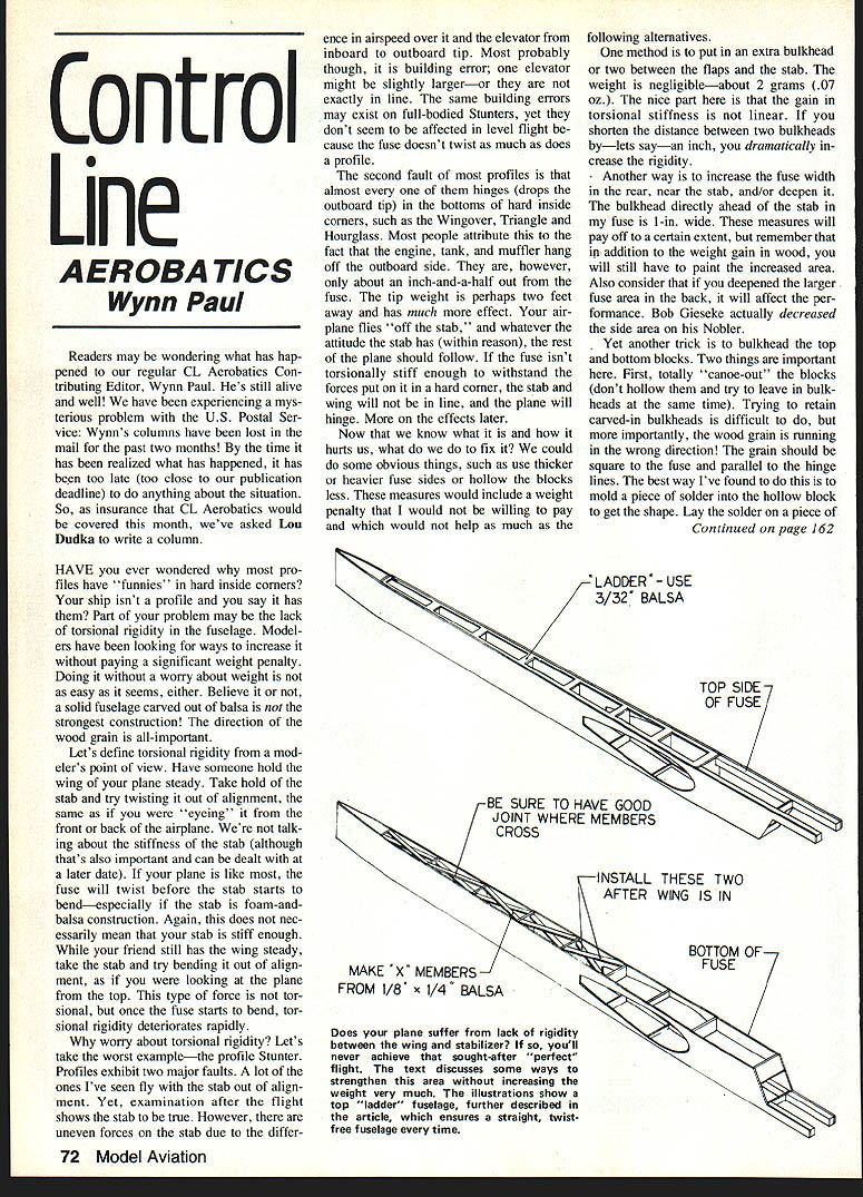
- Use 3/32-in. balsa for the members. Be sure to have a good joint where the members install. The two bottom members can be 1/8 x 1/4 balsa.
- Check the direction of the grain, draw around the pieces with a felt-tip pen, cut them out, and sand to shape.
- Install Hot Stuff and microballoons on bare wood if you use those fillers; the microballoon fillets help relieve stress concentrations in sharp internal corners.
- Be careful not to force bulkheads in, or you will spread the block and it will not fit properly when installed on the fuse.
- When you install the bulkheads, leave them a little long and sand them flush to the block.
- Weight gain: about 3 grams (0.1 oz.) for the top block and 1.5 grams (0.05 oz.) for the bottom block.
- X-bracing between bulkheads (the best solution)
A few people tried triangular gussets in a horizontal plane between the bulkheads and fuse sides; this improved things. What worked best was installing 1/8 x 1/8 balsa strips in an X pattern, top and bottom, between the bulkheads.
- It is extremely important that the two members have a good glue joint where they cross; I can't stress this enough.
- Install the bottom X members first with the fuse weighted down on a flat surface—if you don't, you may build in a twist.
- The increase in strength is phenomenal: it increases torsional rigidity and resistance to bending.
- Weight gain for the X-braces is about 4 grams (0.14 oz.).
For a total of 10.5 grams (0.37 oz.) you have strengthened your fuselage far more than you might imagine. I'm going to use 3/32-in. balsa instead of 1/8-in. for the fuse sides on my next ship and still maintain rigidity; this should totally offset any weight gain.
Some free-flighter who is used to building bird-cage structures is probably chuckling, "If I could have told you so..." If you don't do anything else new on your next Stunter, add the X-braces and you won't be sorry. You have to feel it in your hands to truly grasp what a quantum leap in strength it is.
Building aids and final tips
- Top "ladder" for straight fuses
Try building a fuse with a top "ladder." It weighs next to nothing and practically guarantees a straight fuse. You can cut it out right before installing the top block if you like. It keeps things straight while building and if you later cut out the fuse to install the wing.
Steps:
- Install the first two bulkheads the normal way.
- Cut the ladder from 3/32-in. balsa and draw a centerline on it.
- Put the ladder in the fuse at the centerline so you can line up the fuse with your building board. Pin or weight it down and glue the fuse sides to it.
- You may lift it off and glue it to the fuse later, but leaving it in while the fuse is in the "in the air" assembly is preferred.
- Cut the outboard holes after installing the bulkheads.
Some builders run the ladder the full length of the fuse, glue it in place, then glue the fuse sides to it and drop in motor mounts and the rest of the bulkheads. There's a very slight weight gain, but it absolutely ensures a straight fuse since the first two bulkheads are included in the ladder.
- Thin ply doubler at the engine mount
Glue a thin ply doubler on the fuse bottom where the engine mounts. This spreads motor loads and reduces local crushing. You won't have to worry about perfectly "matched" fuse sides. Even so, avoid using two pieces of wood whose density varies more than two pounds per cubic foot.
Try these methods. Amaze yourself and your friends with that true modeling rarity—a straight fuse—instead of hiding it under the workbench when company arrives.
Many thanks to Lou Dudka for this very insightful article! If the USPS cooperates, we should have Wynn Paul back soon. Please continue to send ideas, news, photos, gripes, or whatever, to Wynn Paul, 1640 Waymirk Dr., Lexington, KY 40504.
Transcribed from original scans by AI. Minor OCR errors may remain.

