
Control Line: Combat
Charlie Johnson
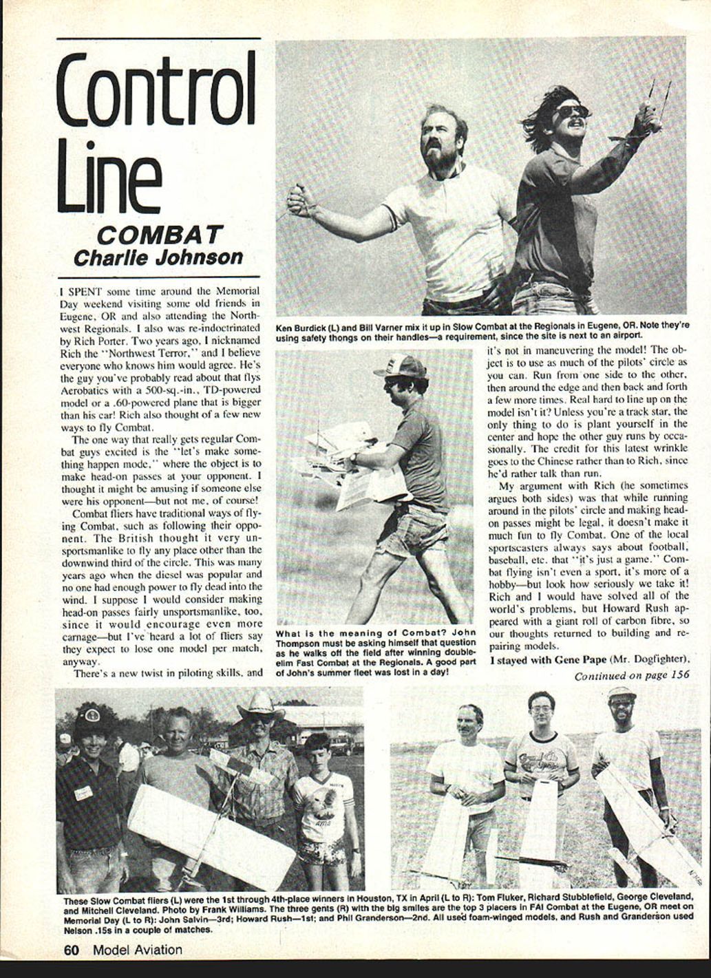
I spent some time around the Memorial Day weekend visiting some old friends in Eugene, OR and also attending the Northwest Regionals. I also was re-indoctrinated by Rich Porter. Two years ago I nicknamed Rich the "Northwest Terror," and I believe everyone who knows him would agree. He's the guy you've probably read about who flies Aerobatics with a 500-sq.-in., TD-powered model or a .60-powered plane that is bigger than his car! Rich also thought of a few new ways to fly Combat.
The one way that really gets regular Combat guys excited is the "let's make something happen" mode, where the object is to make head-on passes at your opponent. I thought it might be amusing if someone else were his opponent—but not me, of course!
Combat fliers have traditional ways of flying Combat, such as following their opponent. The British thought it very unsportsmanlike to fly any place other than the downwind third of the circle. This was many years ago when the diesel was popular and no one had enough power to fly dead into the wind. I suppose I would consider making head-on passes fairly unsportsmanlike, too, since it would encourage even more carnage—but I've heard a lot of fliers say they expect to lose one model per match, anyway.
There's a new twist in piloting skills, and it's not in maneuvering the model! The object is to use as much of the pilots' circle as you can. Run from one side to the other, then around the edge and then back and forth a few more times. Real hard to line up on the model, isn't it? Unless you're a track star, the only thing to do is plant yourself in the center and hope the other guy runs by occasionally. The credit for this latest wrinkle goes to the Chinese rather than to Rich, since he'd rather talk than run.
My argument with Rich (he sometimes argues both sides) was that while running around in the pilots' circle and making head-on passes might be legal, it doesn't make it much fun to fly Combat. One of the local sportscasters always says about football, baseball, etc., that "it's just a game." Combat flying isn't even a sport, it's more of a hobby—but look how seriously we take it! Rich and I would have solved all of the world's problems, but Howard Rush appeared with a giant roll of carbon fibre, so our thoughts returned to building and repairing models.
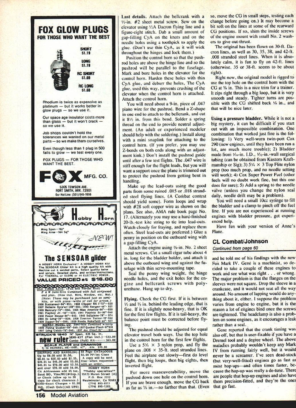
I stayed with Gene Pape (Mr. Dogfighter).
Last details
Attach the bellcrank with a 1/2-in. No. 2 sheet metal screw. Sew on the elevator using 1/8-in. Dacron flying line and a figure-eight stitch. Dab a small amount of gap-filling CyA on the knots and on the needle holes using a toothpick to apply the glue. (Don't use thin CyA, as it will wick throughout the hinges and lock them.)
Position the control horn so that the pushrod holes are above the hinge line and so the pushrod will be parallel to the fuselage. Mark and bore holes in the elevator for the control horn. Harden these holes with thin CyA glue, and deburr the holes. The CyA glue, used this way, prevents crushing of the elevator when the control horn is attached. Attach the control horn.
You will need about a 9-in. piece of .047 piano wire for the pushrod. Bend a Z-shape in one end to attach to the bellcrank, and cut it 8-1/2 in. from this bend. Solder a spring thread on the end to provide neutral adjustment. (An adult or experienced modeler should help with the soldering.) Install along with a mini snaplink for attaching to the control horn. (If you prefer, you may use Z-bends on both ends along with an adjustment kink.) Don't install the pushrod guide until after a few test flights. The .047 wire is stiff enough for the flight loads, but you will want a support once the plane is trimmed out to protect the pushrod from getting bent in handling.
Make up the lead-outs using the good parts from some ruined .015 or .018 stranded steel flying lines. (A Combat contest should yield some.) Form loops and wrap with #28 soft copper wire as shown on the plans. See also AMA rule book page No. 17. (Alternately you may use a hard-finished 20-lb.-test kite string to tie into lead-outs. Watch closely for fraying, and replace them often. Steel lead-outs are preferred.) Glue a penny in position on the outboard wing with a gap-filling CyA.
Attach the engine using 5/8-in. No. 2 sheet metal screws. Cut a small cigar tube about 4 in. long for the bladder holder, and attach it above the outboard wing and against the fuselage with thin servo-mounting tape.
Seal the penny wing weight, the hinge needle holes, and the exit holes for the engine and bellcrank screws with polyurethane. Hang up to dry.
Flying
Check the CG first. If it is between 1/2 and 3/4 in. behind the leading edge, that is fine. If it is slightly nose-heavy, that is OK for the first few flights. If it is tail-heavy, the balance point must be corrected before flying.
The pushrod should be adjusted for equal elevator travel both ways. Use the top hole in the control horn for the first few flights.
Use a 5-1/4 x 3 nylon prop, and fly the plane on .008 x 35-ft. steel stranded lines. Feel the airplane out slowly—first do level flight, then big loops, then big eights, then inverted flight.
For more maneuverability, move the pushrod down one hole on the control horn. If you are brave enough, move the CG back as far as 3/4 in.—no farther than that. (Even so, move the CG in small steps, testing each change before going on.) It may become a bit soft on the lines at some of the rearward CG positions. If so, shim the inside screws of the engine mount with small No. 2 washers to give out-thrust.
The original has been flown on 30-ft. Dacron lines, as well as 30, 35, 38, and 42-ft. .008 stranded steel lines. When it is absolutely calm, it is fun to fly on 42-ft. lines (otherwise, 35 or 38-ft. seems to be about right).
Right now, the original model is rigged to use the top hole on the control horn with the CG at 5/8 in. This is a nice trim for a trainer. It zips right through a big loop, but it is very smooth and steady. Tighter turns are possible with the CG shifted back 1/8 in., and that will be nice later.
Using a pressure bladder
While it is not a big mystery, it can be difficult if you start out with an impossible combination. One combination that worked just fine is the following:
- Very well-worn twin-port Cox 290 (new engines, until they have been run a lot, are much more trouble)
- Bladder made from 1/8-in. I.D., 1/4-in. wall surgical tubing (can be obtained from Kustom Kraftmanship or Sig)
- 5-1/4 x 3 Top Flite nylon prop (too much prop, and no needle setting will work)
- Cox Super Power Fuel (other fuels will no doubt work fine, but this one does for sure)
- Add a sprue to the needle valve (unless you change the nylon seal daily, needle drift may be a problem)
You will need a small 10cc syringe to fill the bladder and a clamp to pinch off the fuel line. If you are not experienced at running engines with bladder pressure, get experienced help.
Have fun with your version of Anne's Plane.
Fox Mark IV and engine break-in
Gene later told me of his findings with the new Fox Mark IV. Gene is a machinist, so he decided to take a couple of these engines to work and see what was right—or wrong. The major problem is that the flanges on the sleeves were not square. Drop the sleeve in the crankcase, and it would not seat all the way around. No amount of lapping would do anything about it. I suppose the problem varies from engine to engine, but it is the reason a lot of engines bind once the screws are tightened. The head clamp is also a problem on some engines, as it encourages a leak rather than a seal.
Gene reported that the crank timing was also off, but that is user-fixable if you have a Dremel tool and a degree wheel. The above maladies probably wouldn't keep any Mark IV from running fairly well, but it would never be a screamer. I've seen dead-stock (but very-well-fitted) engines go as fast as most hop-ups—and oftentimes faster, because the hop-up was really a de-tune. There are people that hot-up engines and also have them precision-fitted, and they're the ones that go fast.
I've had good luck over the years using jeweler's rouge to break in engines. You can purchase the rouge at hardware stores for a couple of bucks. I've had one stick of the stuff for 15 years and have hardly used a quarter of it. Scrape off a bit from an end and mix it with 3-in-1 oil. I lap the piston and liner together while the engine is disassembled. This compound is not very abrasive, and it would take a long time to lap too much. Fox makes a more abrasive compound called Garnet, but this should be used with caution. The insert or head can be lapped to the cylinder using either compound. I stick a plug in the insert and then use an electric drill to speed up the process.
All the hop-up articles tell you about how to grind out the inside of the crank, but you can ignore all that until you've won a few contests and can get "Texas" starts every time. Those instant starts come from a well-fitted engine and a mighty arm.
Be sure to wash out the engine with a safe solvent. It will be easy to spot a bad bearing if the engine is dry, since a lot of oil would mask the problem. Fortunately, bearings for the Fox are standard size and available from either Fox or a bearing supply house. Basically, all I'd do to an engine would be classed under "clean and inspect," other than the lapping.
The jeweler's rouge is the best thing I've found to aid break-in. Take a cotton swab and put a little of the mixture in the exhaust port. Flip the engine over a few times to distribute the mixture, then run the engine for a short burst (just on the prime is OK). Put more rouge mixture in the exhaust and run for a few minutes at a time. This is going to be messy! Keep the test stand away from everything.
You'll notice that there is a shiny area at the top of the piston and the inside of the cylinder. As the piston passes the exhaust port, you'll also notice that it seals right then, rather than going farther up the cylinder. The engine needs to have lots and lots of running time on it before it is ready for Combat. If the engine is run fast (but not overclean), it will grow into its proper fit. Do not run the engine blubbering rich, as this seems to loosen the rod and wrist-pin-to-piston fit. If you took the rod/piston assembly apart, I hope you worked inside a see-through plastic bag so the little wrist-pin retaining clips didn't fly away. When you put the retainer clips back in the piston, you should count off most of the bent part and orient the remainder pointing up toward the top of the piston.
Another technique for break-in is to run the engine a couple times and then tear it down and buff the high spots on the piston with a Dremel tool and the cloth polishing tool using the rouge mixture. This is a lot more work and you take the chance of losing a seal someplace. Engines that seal right after closing the exhaust seem to make superior Slow Combat engines and nice-starting Fast Combat engines. The reason that a lot of the very fast engines have loose fits is that they distort when they get hot and also from the internal stresses. Precision fitting and machining doesn't guarantee the engine staying in that alignment when producing its maximum power!
Myles Lawrence was seen using a Henry Nelson crank in his Fox .36. The case was bored and new bearings installed, so it's not in the do-it-yourself category. The engine was very fast. Whether these cranks will be available, I'll probably know by next column.
Charlie Johnson, 3716 Ingraham St., San Diego, CA 92109.
Transcribed from original scans by AI. Minor OCR errors may remain.

