
Navy Carrier
Richard L. Perry
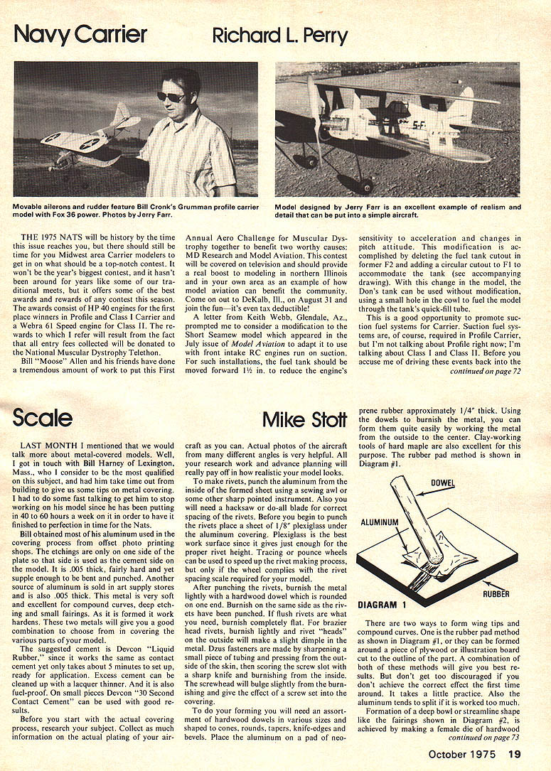
The 1975 NATS will be history by the time this issue reaches you, but there should still be time for you Midwest area Carrier modelers to get in on what should be a top-notch contest. It won't be the year's biggest contest, and it hasn't been around for years like some of our traditional meets, but it offers some of the best awards and rewards of any contest this season.
The awards consist of HP 40 engines for the first place winners in Profile and Class I Carrier and a Webra 61 Speed engine for Class II. The rewards to which I refer will result from the fact that all entry fees collected will be donated to the National Muscular Dystrophy Telethon. Bill "Moose" Allen and his friends have done a tremendous amount of work to put this First Annual Aero Challenge for Muscular Dystrophy together to benefit two worthy causes, MD Research and Model Aviation. This contest will be covered on television and should provide a real boost to modeling in northern Illinois and in your own area as an example of how model aviation can benefit the community. Come on out to DeKalb, Ill., on August 31 and join the fun — it's even tax deductible!
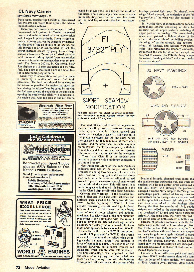
A letter from Keith Webb, Glendale, Az., prompted me to consider a modification to the Short Seamew model which appeared in the July issue of Model Aviation to adapt it to use with front-intake RC engines run on suction. For such installations, the fuel tank should be moved forward 1½ in. to reduce the engine's sensitivity to acceleration and changes in pitch attitude. This modification is accomplished by deleting the fuel tank cutout in former F2 and adding a circular cutout to F1 to accommodate the tank (see accompanying drawing). With this change in the model, the Don's tank can be used without modification, using a small hole in the cowl to fuel the model through the tank's quick-fill tube.
This is a good opportunity to promote suction fuel systems for Carrier. Suction fuel systems are, of course, required in Profile Carrier, but I'm not talking about Profile right now; I'm talking about Class I and Class II. Before you accuse me of driving these events back into the CL Navy Carrier Dark Ages, consider the benefits of pressurized fuel systems and weigh these against the advantages of suction systems. There are two primary advantages to using pressurized fuel systems in Carrier: increased power and reduced sensitivity to acceleration and changes in pitch attitude. There is some increase in power that can be achieved by increasing the area of the air intake on an engine, but this increase is often exaggerated. In fact, the power increase caused by going from a large suction intake to a "sewer pipe" sized pressure intake is small. Many Speed flyers use suction because it is easier to manage; they even set records. I've flown a .300 sq. in. California Slow Rat airplane at 115 mph on suction and 5% nitro fuel. The point is that intake size is a small factor in determining engine output. Sensitivity to acceleration and pitch attitude is primarily a matter of proper fuel tank placement. The fuel tank should be as close to the intake as possible. An engine that goes too lean during the take-off can be cured by moving the fuel tank toward the outside of the circle and opening the needle valve slightly to compensate. An engine that runs too lean in the air can be cured by moving the tank toward the inside of the circle. These same adjustments can be made by substituting wider or narrower fuel tanks on the model — just make the fuel tank accessible. I've used all kinds of throttle arrangements: meters, on-off pressure, crankcase pressure, bladders, you name it. I have reached one conclusion — suction is easier! I still hang on to my pressure systems for the few extra points they can give, but they require a lot more work to adjust and maintain than the suction systems on my Profile. Couple their simplicity with availability and low cost and suction systems offer some definite advantages.
Control Line: Navy Carrier
There are two primary advantages to using pressurized fuel systems in Carrier: increased power and reduced sensitivity to acceleration and changes in pitch attitude. There is some increase in power that can be achieved by increasing the area of the air intake on an engine, but this increase is often exaggerated. In fact, the power increase caused by going from a large suction intake to a "sewer pipe" sized pressure intake is small. Many Speed flyers use suction because it is easier to manage; they even set records. I've flown a .300 sq. in. California Slow Rat airplane at 115 mph on suction and 5% nitro fuel. The point is that intake size is a small factor in determining engine output.
Sensitivity to acceleration and pitch attitude is primarily a matter of proper fuel tank placement. The fuel tank should be as close to the intake as possible. An engine that goes too lean during the take-off can be cured by moving the fuel tank toward the outside of the circle and opening the needle valve slightly to compensate. An engine that runs too lean in the air can be cured by moving the tank toward the inside of the circle. These same adjustments can be made by substituting wider or narrower fuel tanks on the model — just make the fuel tank accessible. I've used all kinds of throttle arrangements: meters, on-off pressure, crankcase pressure, bladders, you name it. I have reached one conclusion — suction is easier! I still hang on to my pressure systems for the few extra points they can give, but they require a lot more work to adjust and maintain than the suction systems on my Profile. Couple their simplicity with availability and low cost and suction systems offer some definite advantages for the newcomer to Class I and Class II or the modeler who desires to compete with a minimum expenditure of time and money.
New Products: More on the G-S Products bellcrank described in the August issue. G-S Products is adding two new control units to its line. These will be upright and inverted short-span units with the elevator bellcrank turned around to place the elevator control arm toward the outside of the circle. This will result in a more compact unit that will fit better into the smaller Class I airplanes like the Short Seamew.
Coloring and Markings: In the previous column I discussed the basic color schemes and national insignia used on U.S. Navy aircraft from WW I to the beginning of WW II. I have avoided discussing aircraft markings in detail because I want to first cover the very broad areas of overall color schemes and national type markings. I consider these as the bare minimum requirements for complying with the rules. I hope to cover more detailed markings in later columns, particularly the very colorful fleet aircraft markings used between WW I and WW II. This month I will cover the WW II time period.
As the U.S. prepared for WW II, the overall silver color scheme and the yellow wing coloring carried on many aircraft was dropped in favor of camouflage paint. The silver color was retained, however, on all-metal trainers and transports which simply were left unpainted. The first camouflage paint appeared in 1941 and consisted of a grey-green color on the upper surfaces and a light gray on the undersurfaces. In 1943 the Navy changed to a three-tone blue-gray camouflage scheme consisting of dark bluish gray coloring for all upper surfaces including the upper part of the fuselage. The lower fuselage and sides were painted a lighter shade of blue-gray as were the undersides of the wings and the bottom surfaces of carrier aircraft. The bottoms of wings, tail surfaces and fuselage were painted light gray. This remained the standard camouflage throughout the war for all aircraft except those assigned to carriers. In 1944 the Navy adopted an overall "midnight blue" color as standard for carrier aircraft.
National insignia changed even more than the paint schemes during the war. The white star in a dark blue circle with a red center circle continued in U.S. use until May 1942. Because of possible confusion with Japanese markings, the red center was removed in June 1942. A year later the star-and-bar emblem with a red border was adopted, and the border was later removed. Rudder stripes and other variations were used at different times and on different types; consult period references for specific placement and color details.
The next column will cover paint and markings from WW II to the present along with some ideas on design of Profile models. Send correspondence to: 5016 Angelita Ave., Dayton, Ohio 45424.
Transcribed from original scans by AI. Minor OCR errors may remain.

