
Control Line: Navy Carrier
Richard L. Perry
I STARTED OUT in my last column to write about some of the features of our models that are different from other CL models. I am hoping to remove some of the mystery of our event for those who haven't yet tried it and, at the same time, I will try to present a variety of methods that might help the more experienced modeler around a problem area or that might stimulate a new idea. This column will deal with tail hooks, flaps, and ailerons. I chose to lump these items together because they are usually connected to one another in some way.
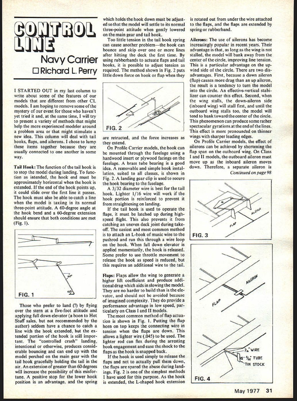
Tail Hook: The function of the tail hook is to stop the model during landing. To function as intended, the hook end must be approximately horizontal when the hook is extended. If the end of the hook points up, it could slide over the first line it passes. The hook must also be able to catch a line when the model is taxiing in its normal three-point attitude. A 60-degree angle at the hook bend and a 60-degree extension should ensure that both conditions are met (Fig. 1).
Those who prefer to land over the stern at a five-foot altitude and applying full down elevator (a boon to Hot Stuff sales, but not recommended by the author) seldom have a chance to catch a line with the hook extended, but the extended portion of the hook is still important. The "controlled crash" landing, intentional or otherwise, produces considerable bouncing and can end up with the model perched on the main gear with the tail hook gracefully holding the tail in the air. An extension of greater than 60 degrees will increase the possibility of this misfortune. A positive stop for the lower hook position is an advantage, and the spring which holds the hook down must be adjusted so that the model will settle to its normal three-point attitude when gently lowered on the main gear and tail hook.
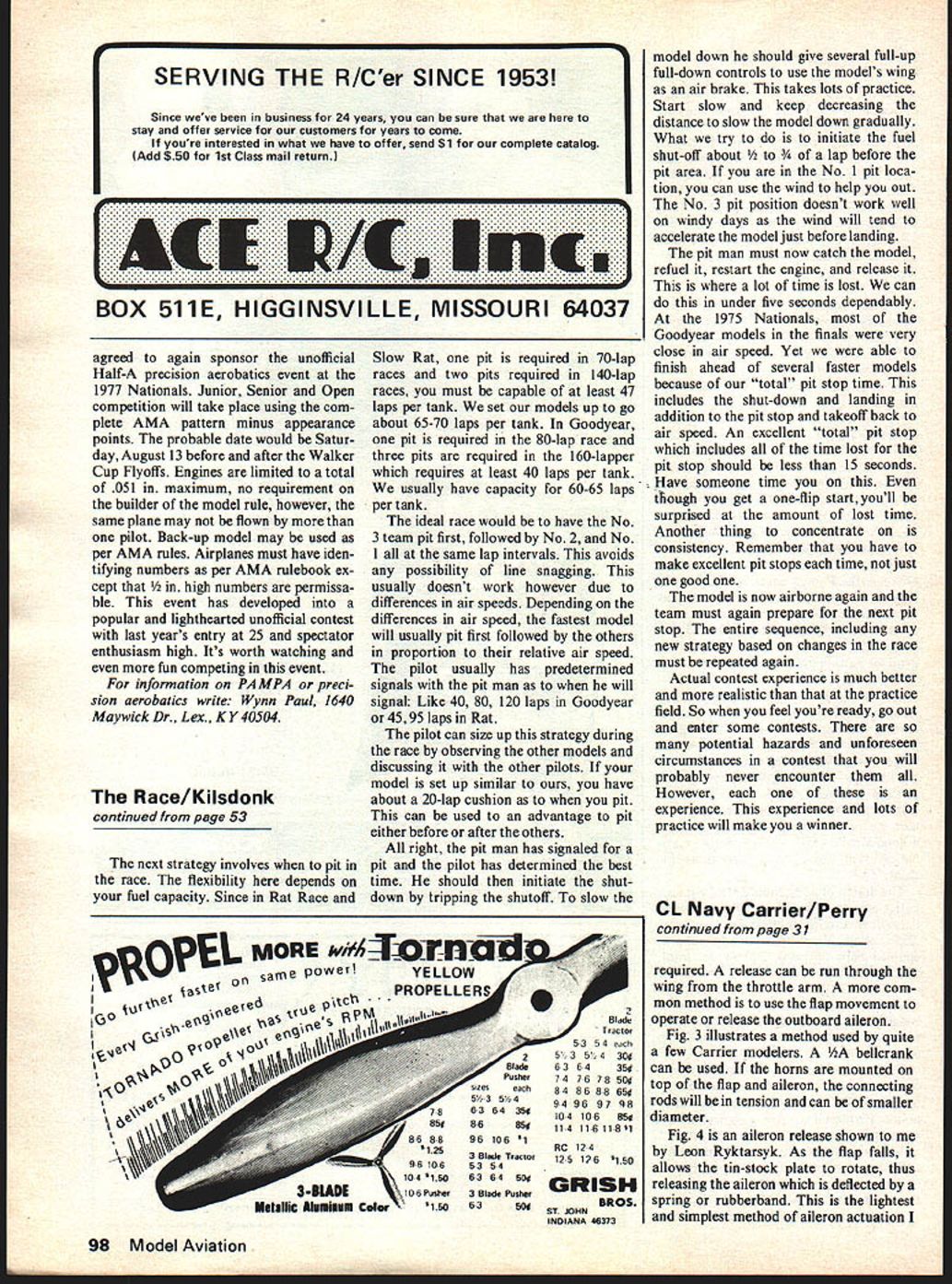
Too little tension in the tail hook spring can cause another problem—the hook can bounce and skip over one or more lines after hitting the deck the first time. By using rubberbands to actuate flaps and tail hooks, it is possible to adjust tension as required. The method shown in Fig. 2 puts little down force on hook or flap when they are retracted, and the force increases as they extend.
On Profile Carrier models, the hook can be mounted through the fuselage using a hardwood insert or plywood facings on the fuselage. A brass tube bearing is a good idea. A removable and simple hook installation, suited to all classes, is shown in Fig. 2. A landing gear clip is used to secure the hook bearing to the fuselage.
A 3/32 diameter wire is best for the tail hook. Lighter 1/16 wire will work if the hook portion is reinforced to prevent it from straightening on landing.
If the tail hook is used to operate the flaps, it must be latched up during high-speed flight. This also prevents it from catching an uneven deck joint during take-off. The easiest and most common method is to attach an L-hook of music wire to the pushrod and run this through a wire loop on the hook. When full down elevator is applied momentarily, the hook is released. Some prefer to use throttle movement to release the hook as speed is reduced, but this requires an additional wire to the tail.
Flaps: Flaps allow the wing to generate a higher lift coefficient and produce additional drag which aids in slowing the model. They are no harder to build than is the elevator, and should not be avoided because of imagined complexity. They do provide a performance advantage in low speed, particularly on Class I and II models.
The most common method of flap actuation is shown in Fig. 1. Putting the flap horn on top keeps the connecting wire in tension when the flaps are down. This allows a lighter wire (.045) to be used. The lighter rod can flex during the arresting hook engagement and ease the shock to the flaps as the hook is snapped back.
If the hook is used simply to release the flaps and not to actually pull them down, the flaps are spared the abuse during landings. Fig. 2 is one of the simplest methods I have used for this purpose. As the hook is extended, the L-shaped hook extension is rotated out from under the wire attached to the flaps, and the flaps are extended by spring or rubberband.
Ailerons: The use of ailerons has become increasingly popular in recent years. Their advantage is that, as long as the wing is not stalled, the model will bank away from the center of the circle, improving line tension. This is a particular advantage on the upwind side of the circle. There are two disadvantages. First, because a down aileron (flap) causes more drag than an up aileron, the result is a tendency to turn the model into the circle. An effective vertical stabilizer can counter this effect. Second, when the wing stalls, the down-aileron side (inboard wing) will stall first, and until the outboard wing stalls too, the model will tend to bank toward the center of the circle. This phenomenon can produce some rather spectacular gyrations at the end of the lines. This effect is more pronounced on thinner wings with sharper leading edges.
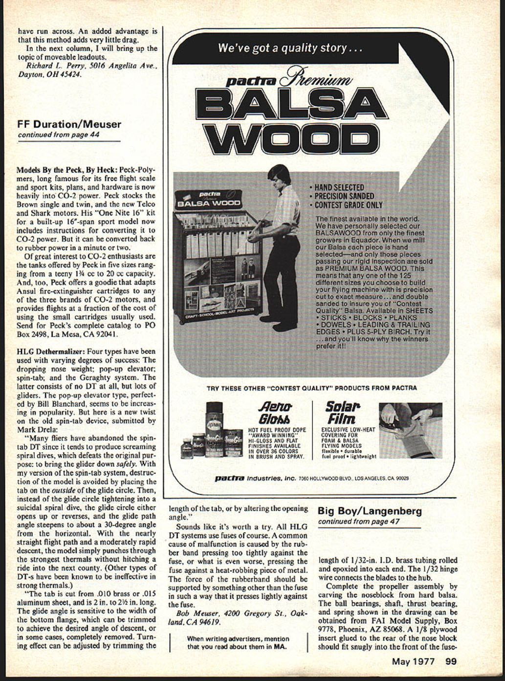
On Profile Carrier models, the effect of ailerons can be achieved by shortening the flap span on the outboard wing. On Class I and II models, the outboard aileron must move up as the inboard aileron moves down. Therefore, a separate aileron is required. A release can be run through the wing from the throttle arm. A more common method is to use the flap movement to operate or release the outboard aileron.
Fig. 3 illustrates a method used by quite a few Carrier modelers. A 1/4" bellcrank can be used. If the horns are mounted on top of the flap and aileron, the connecting rods will be in tension and can be of smaller diameter.
Fig. 4 is an aileron release shown to me by Leon Rytkarsyk. As the flap falls, it allows the tin‑stock plate to rotate, thus releasing the aileron which is deflected by a spring or rubberband. This is the lightest and simplest method of aileron actuation I have found. I started out last column to write about some features of Navy Carrier models different from other CL models. I am hoping to remove some mystery. At the same time I will try to present a variety of methods which might help the experienced modeler around problem areas and might stimulate new ideas. This column will deal with tail hooks, flaps and ailerons. I chose to lump these items together because they are usually connected to one another some way.
Tail hook
Tail hook function — The tail hook stops the model during landing. For the hook to function as intended the hook end must be approximately horizontal when extended. The end of the hook must point up enough to slide over the first line as it passes. The hook must also be able to catch the line when the model is taxiing in its normal three‑point attitude. A 60‑degree bend and a 60‑degree extension should ensure both conditions are met (Fig. 1).
I prefer landing over the stern from about five feet altitude, applying full down elevator just before boom. Hot‑stuff sales recommended this; the author seldom has the chance to catch the line. The extended portion of the hook is still important for a controlled crash landing. Otherwise one gets considerable bouncing and can end up with the model perched on the main gear with the tail hook gracefully holding the tail airframe. An extension greater than 60 degrees will increase the possibility of misfortune. A positive stop at the lower hook position has the advantage that a spring holds the hook down; the hook must be adjusted so the model will settle into its normal three‑point attitude when gently lowered onto the main gear and tail hook.
Too little tension on the tail‑hook spring can cause another problem — the hook can bounce and skip over the lines after hitting the deck. When using rubber bands to actuate flaps or tail hooks, it is possible to adjust the tension required. The method shown in Fig. 2 puts little down force on the hook with the flap retracted; the force increases as the flap is extended.
On profile Carrier models the hook can be mounted through the fuselage using a hardwood insert and plywood facings. A brass tube bearing in the fuselage is a good idea for a removable, simple hook installation suited to the classes shown. In Fig. 2 a landing‑gear clip is used to secure the hook bearing in the fuselage. 3/32" diameter wire is the best tail hook. Lighter 1/16" wire will work for the hook portion but should be reinforced to prevent straightening on landing. Tail hooks used to operate flaps must be latched up during high‑speed flight; this also prevents catching an uneven deck joint during takeoff.
The easiest and most common method is to attach an L‑hook of music wire to the pushrod and run the pushrod through a wire loop on the hook. With full down elevator applied momentarily the hook is released. Some prefer to use throttle movement to release the hook; speed reduction requires additional wire and linkage.
Flaps
Flaps allow the wing to generate a higher lift coefficient and produce additional drag to aid in slowing the model. They are no harder to build than elevators and should be avoided only because imagined complexity might deter modelers from adding a real performance advantage at low speed, particularly on Class II models. A common method of flap actuation is shown in Fig. 1. Putting the flap horn on top keeps the connecting wire in tension with the flaps down and allows the use of lighter wire (0.045"). A lighter rod can flex during an arresting hook engagement to ease the shock when the flap snaps back. If the hook is used simply to release the flaps, the flaps are spared some abuse during landings.
Fig. 2 shows the simplest methods I have used for purpose. As the hook is extended, an L‑shaped hook extension is rotated out under the wire attached to the flaps; the flaps are held extended by a spring or rubber band.
Ailerons
The use of ailerons has become increasingly popular in recent years. The advantage is that on a long wing a stalled model will bank away from the center of the circle, improving line tension — a particular advantage on the up‑wind side of the circle. There are two disadvantages. First, because the down aileron acts like a flap, it causes drag; the up aileron produces a tendency to turn into the circle. An effective vertical stabilizer can counter this effect. Second, the wing stalls on the down‑aileron side: the inboard wing will stall first and, until the outboard wing stalls too, the model will tend to bank toward the center of the circle. This phenomenon can produce some rather spectacular gyrations at the end of the lines. The effect is more pronounced on thinner wings with sharper leading edges.
On profile Carrier models the effect of ailerons can be achieved by shortening the flap span on the outboard wing. On Class I and II models the outboard aileron must move up while the inboard aileron moves down. Therefore separate ailerons are required. A release can be run through the wing from the throttle arm, but a more common method is to use the flap movement to operate or release the outboard aileron.
Fig. 3 illustrates a method used by quite a few Carrier modelers. A 1/4" bellcrank can be used. If the horns are mounted on top of the flap and aileron, the connecting rods will be in tension and can be of smaller diameter. Fig. 4 is an aileron release shown to me by Leon Rytkarsyk. As the flap falls, it allows the tin‑stock plate to rotate, thus releasing the aileron which is deflected by a spring or rubber band. This is the lightest and simplest method of aileron actuation I have found.
Transcribed from original scans by AI. Minor OCR errors may remain.

