
CONTROL LINE NAVY CARRIER
Dick Perry 7005 Del Oso Court NE, Albuquerque, NM 87109
Abstract
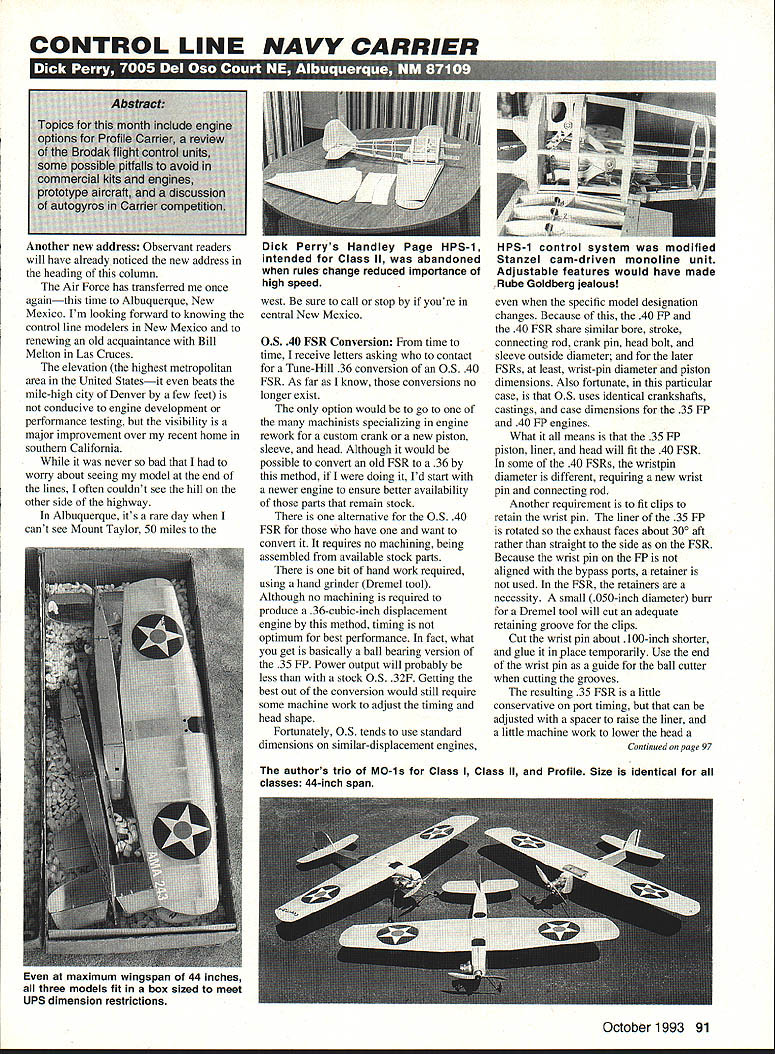
Topics for this month include engine options for Profile Carrier, a review of the Brodak flight control units, some possible pitfalls to avoid in commercial kits and engines, prototype aircraft, and a discussion of autogyros in Carrier competition.
Another new address Observant readers will have already noticed the new address in the heading of this column. The Air Force has transferred me once again—this time to Albuquerque, New Mexico. I'm looking forward to meeting the control line modelers in New Mexico and to renewing an old acquaintance with Bill Melton in Las Cruces.
The elevation (the highest metropolitan area in the United States—it even beats the mile-high city of Denver by a few feet) is not conducive to engine development or performance testing, but the visibility is a major improvement over my recent home in southern California. While it was never so bad that I had to worry about seeing my model at the end of the lines, I often couldn't see the hill on the other side of the highway. In Albuquerque, it's a rare day when I can't see Mount Taylor, 50 miles to the west. Be sure to call or stop by if you're in central New Mexico.
O.S. .40 FSR Conversion
From time to time I receive letters asking who to contact for a Tune-Hill .36 conversion of an O.S. .40 FSR. As far as I know, those conversions no longer exist. The only option would be to go to one of the many machinists specializing in engine rework for a custom crank or a new piston, sleeve, and head. Although it would be possible to convert an old FSR to a .36 by this method, if I were doing it I'd start with a newer engine to ensure better availability of those parts that remain stock.
There is one alternative for the O.S. .40 FSR for those who have one and want to convert it. It requires no machining, being assembled from available stock parts. There is one bit of hand work required, using a hand grinder (Dremel tool).
Although no machining is required to produce a .36-cubic-inch displacement engine by this method, timing is not optimum for best performance. In fact, what you get is basically a ball-bearing version of the .35 FP. Power output will probably be less than with a stock O.S. .32F. Getting the best out of the conversion would still require some machine work to adjust the timing and head shape.
Fortunately, O.S. tends to use standard dimensions on similar-displacement engines. What that means is that the .35 FP piston, liner, and head will fit the .40 FSR. In some of the .40 FSRs, the wristpin diameter is different, requiring a new wristpin and connecting rod. Another requirement is to fit clips to retain the wristpin. The liner of the .35 FP is rotated so the exhaust faces about 30° aft rather than straight to the side as on the FSR. Because the wristpin on the FP is not aligned with the bypass ports, a retainer is not used. In the FSR, the retainers are a necessity.
A small (.050-inch-diameter) burr for a Dremel tool will cut an adequate retaining groove for the clips. Cut the wristpin about .100-inch shorter, and glue it in place temporarily. Use the end of the wristpin as a guide for the ball cutter when cutting the grooves. The resulting .35 FSR is a little conservative on port timing, but that can be adjusted with a spacer to raise the liner and a little machine work to lower the head.
CL NAVY CARRIER / PERRY
Digging deeper — kits and engines
We've all heard the advice "If you can't say something good about a person, don't say anything at all." I've tried to follow that maxim on products I mention in this column, and that's particularly true if a company sends me a product to evaluate. If I can't recommend the product, I tell the reader, not the manufacturer, nor the world.
I've deviated from that policy a little lately, such as when I described the Magnum Pro .36 (.37) engine in my last column. It is a good engine, but it's bigger than advertised and, therefore, not suitable for our Profile Carrier event. To their credit, the folks at Hobby Shack were very cooperative in talking about the engine and have been discussing the possibility of a size change with the manufacturer—no information yet.
This month I'm going to deviate again—mentioning products which, on the surface, appear to be good bets for Carrier competition, but that fall short under closer scrutiny. My objective is to help readers avoid spending time and money on products that fail to meet expectations as far as Navy Carrier events are concerned.
Ron Duly recently spent some time in England and visited the Irvine engine plant. He was pleasantly surprised to learn that the company is planning to market a front-intake, throttle-equipped .36 engine, primarily for the helicopter market. Unfortunately, like the Magnum, the Irvine is planned for a displacement greater than the .360-cubic-inch limit of the Profile Carrier event. Ron talked about our requirements, and I can't report on the actual production configuration at this time. Just be sure to inquire about displacement and suitability if you are considering the purchase of one of these engines. I'll publish more information as production plans become available.
I have been continually on the lookout for kits that could be readily converted to Class I and Class II competition. I have discussed the Sterling Corsair—previously the only production kit that satisfied the scale requirements of our events—in prior columns. The smaller size of the Sterling kit (36-inch span, 240-square-inch area) is slightly below current norms, and the construction is a little light. It is designed around a .10 engine, and the move up to a .40 or .46 requires significant structural modification.
I was encouraged to find that House of Balsa manufactures an AT-6 (44-inch span) and a P-51D (43-inch span) that are designed to accommodate .21 engines. Their size and construction are more appropriate for an easy modification to Carrier use. Unfortunately, both kits fit more into the fun-scale category. They are not even close to the scale requirements of our events.
Global Distributing's P-39 Airacobra was the next kit to catch my eye when it was listed in new-product selections of some of the model magazines. Its span (40.5 inches) and area (297 square inches) were right on the money for scale proportions, so I ordered a P-39 to check it out. Once again, I was disappointed. The Global P-39 is too far from scale to be useful as either a P-39 or as an XFL-1 Airabonita.
Navy aircraft eligibility (AT-6, P-51, P-39)
You may wonder about the AT-6, P-51, and P-39 as candidates for Navy Carrier events, since they were U.S. Army airplanes. All qualify for our events, as all have operated or been tested aboard aircraft carriers.
- North American AT-6 (SNJ): Purchased by the Navy as the SNJ and used for training. Of the thousands produced, a few SNJ-5Cs were equipped with arresting hooks for deck-landing training. Berkeley used to make a CL kit of the SNJ, and at least two construction articles have been published. Vern Shroeder's model appeared in the May 1960 Model Airplane News. It spanned 43 inches, for a wing area of 260 square inches—great for either Class I or Class II. The plan may no longer be available, but MAN might help.
- Another AT-6 (SNJ) appeared in Air Trails in January 1950. It was slightly smaller, with a 42-inch span. Dick Gleason (Gleason Enterprises, 1106 10th Dr. SE, Austin, MN 55912; Tel.: [507] 437-3781) has reprints of the plans. His reprint is well worth the cost (it was $2.75 last time I ordered one). It contains many models suitable for our events with very little modification. Many were designed as Carrier models; others were intended as scale models but could be modified easily to incorporate tail hooks and appropriately lengthened structures.
- P-51 Mustang: The P-51D was tested extensively for carrier use. One Mustang was equipped with catapult and arresting gear and was tested both on the simulated deck at the Philadelphia Ship Experimental Unit and aboard USS Shangri-La in 1944. John Blum's P-51D for Class I Navy Carrier was published in American Aircraft Modeler in June 1967 (28-inch span, 135 square inches). A larger P-51B model (37-inch span, about 235 square inches) appeared in American Modeler in May 1962 and could be turned into a D variant. Gleason has the plan for this one, too.
- Bell P-39 Airacobra / XFL-1 Airabonita: The XFL-1 looks like a conventional-gear P-39 with a tail hook, but there were many subtle differences between the two aircraft. The U.S. Navy owned two P-39s designated F2L-1K and used them as targets, not for carrier suitability testing. To qualify the P-39 as a Navy Carrier model, one must look to England: the British Royal Navy borrowed the RAF's fourth P-39 (AH573), modified it, and tested it aboard a carrier as part of tricycle-gear suitability tests.
Charles Reeves published a 30-inch-span, 160-square-inch XFL-1 in the 1960s; I'd appreciate hearing from any readers who can identify the magazine and date. I know of no P-39 plans other than my own 140-square-inch Class I design.
New French carrier aircraft
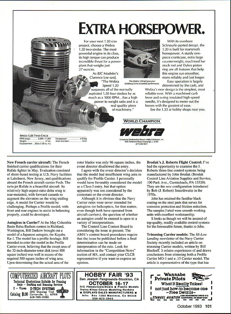
The French finished carrier qualifications for their Rafale fighter in May. Evaluation consisted of shore-based testing at U.S. Navy facilities at Lakehurst, New Jersey, and qualifications aboard the French aircraft carrier Foch. The twin-jet Rafale is a beautiful aircraft. Its relatively high-aspect-ratio delta wing is rear-mounted, with forward canards to augment the elevators on the wing trailing edge. A model for Carrier would be challenging. Perhaps a Profile model, with front and rear engines to assist in balancing properly, could be developed.
Autogyros in Carrier?
At the May Columbia Basin Balsa Bashers contest in Richland, Washington, Bill Darkow brought out a model of a Japanese autogyro, the Kayaba Ka-1. The model had a profile fuselage. Bill intended to enter the model in the Profile Carrier event, believing that the swept area of the 32-inch-diameter rotor disk (over 800 square inches) was well in excess of the required 300 square inches of wing area. Upon determining that the actual area of the rotor blades was only 96 square inches, the event director disallowed the entry.
I agree with the event director's decision that the model had insufficient wing area to qualify for Profile Carrier. I personally would have favorably considered the model as a Class I entry, but that option apparently was not considered by the contestant or the event director.
Although it is obvious that the Navy Carrier rules were never intended for autogyros or helicopters, for that matter, even though both have operated from aircraft carriers, the question of whether an autogyro could be entered is open to a variety of interpretations. The Control Line Contest Board is considering the issue at present. The AMA's contest board procedures require that the issue be published before a final determination can be made on interpretation of the rule. Look for information in the "Competition News" section of Model Airplane News, and contact your CLCR representative if you want to express an opinion.
Brodak's J. Roberts flight control
I've had the opportunity to examine the J. Roberts three-line control systems being manufactured by John Brodak (Brodak Control Line Aviation Supplies and Service, 100 Park Ave., Carmichaels, PA 15320). They are the new configuration introduced by Bob (J. Robert) Smurthwaite in the 1970s.
John has retained the familiar black coating on the steel parts that serves for corrosion protection and friction reduction. The samples I tried were smooth-working units with excellent workmanship. It looks as though we will be assured of top-quality, readily available control systems for the foreseeable future, thanks to John.
Trimming Carrier models
The Hi-Low Landing newsletter of the Navy Carrier Society recently included an article on trimming Carrier models, written by Bill Bischoff. It relates experiences and draws conclusions from trimming both a Profile Carrier MO-1 and a .15 Carrier model. The article is representative of the type that has become common in the newsletter since Mike Pugh took over editorial duties.
To become a member of the Navy Carrier Society and receive the bimonthly newsletter, send dues of $6 to Bill Bischoff at his new address: 3734 Truesdell, Dallas, TX 75244.
Transcribed from original scans by AI. Minor OCR errors may remain.

