
CONTROL LINE NAVY CARRIER
Dick Perry, 7005 Del Oso Court, Albuquerque, NM 87109-2930
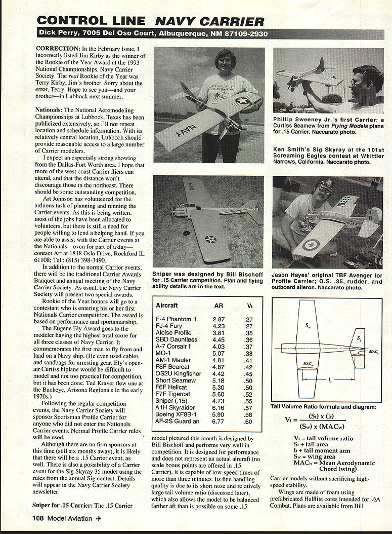
Correction
In the February issue, I incorrectly listed Jim Kirby as the winner of the Rookie of the Year Award at the 1993 National Championships, Navy Carrier Society. The real Rookie of the Year was Terry Kirby, Jim's brother. Sorry about the error, Terry. Hope to see you—and your brother—in Lubbock next summer.
Nationals
The National Aeromodeling Championships at Lubbock, Texas has been publicized extensively, so I won't repeat location and schedule information. With its relatively central location, Lubbock should provide reasonable access to a large number of Carrier modelers.
I expect an especially strong showing from the Dallas–Fort Worth area. I hope that more of the west coast Carrier fliers can attend, and that the distance won't discourage those in the northeast. There should be some outstanding competition.
Art Johnson has volunteered for the arduous task of planning and running the Carrier events. As this is being written, most of the jobs have been allocated to volunteers, but there is still a need for people willing to lend a helping hand. If you are able to assist with the Carrier events at the Nationals—even for part of a day—contact Art at 1818 Oslo Drive, Rockford, IL 61108; Tel.: (815) 398-3490.
In addition to the normal Carrier events, there will be the traditional Carrier Awards Banquet and annual meeting of the Navy Carrier Society. As usual, the Navy Carrier Society will present two special awards:
- Rookie of the Year: Honors a contestant who is entering his or her first Nationals Carrier competition. The award is based on performance and sportsmanship.
- Eugene Ely Award: Goes to the modeler having the highest total score for all three classes of Navy Carrier. It commemorates Eugene Ely, the first man to fly from and land on a Navy ship.
Following the regular competition events, the Navy Carrier Society will sponsor Sportsman Profile Carrier for anyone who did not enter the Nationals Carrier events. Normal Profile Carrier rules will be used.
Although there are no firm sponsors at this time (still six months away), it is likely that there will be a .15 Carrier event as well. There is also a possibility of a Carrier event for the Sig Skyraider .35 model using the rules from the annual Sig contest. Details will appear in the Navy Carrier Society newsletter.
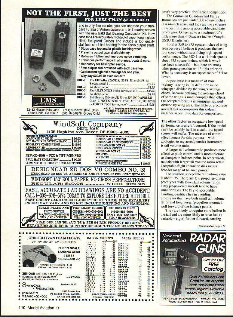
Sniper for .15 Carrier
The .15 Carrier model pictured this month is designed by Bill Bischoff and performs very well in competition. It is designed for performance and does not represent an actual aircraft (no scale bonus points are offered in .15 Carrier). It is capable of low-speed times of more than three minutes. Its fine handling quality is due to its short nose and relatively large tail volume ratio (discussed later), which also allows the model to be balanced farther aft than is possible on some .15 models.
They allow construction without sacrificing high-speed stability. Wings are made of foam using prefabricated Halflite cores intended for 1/2A Combat.
Prototype Data (Aspect Ratio and Tail Volume Ratio)
- F-4 Phantom II — AR: 2.87, Vt: .27
- FJ-4 Fury — AR: 4.23, Vt: .27
- Aloise Profile — AR: 3.81, Vt: .35
- SBD Dauntless — AR: 4.45, Vt: .36
- A-7 Corsair II — AR: 4.03, Vt: .37
- MO-1 — AR: 5.07, Vt: .38
- AM-1 Mauler — AR: 4.81, Vt: .41
- F8F Bearcat — AR: 4.87, Vt: .42
- OS2U Kingfisher — AR: 4.42, Vt: .45
- Short Seamew — AR: 5.18, Vt: .50
- F6F Hellcat — AR: 5.30, Vt: .50
- F7F Tigercat — AR: 5.60, Vt: .52
- Sniper (.15) — AR: 4.73, Vt: .55
- A1H Skyraider — AR: 6.16, Vt: .57
- Boeing XF8B-1 — AR: 5.90, Vt: .58
- AF-2S Guardian — AR: 6.77, Vt: .60
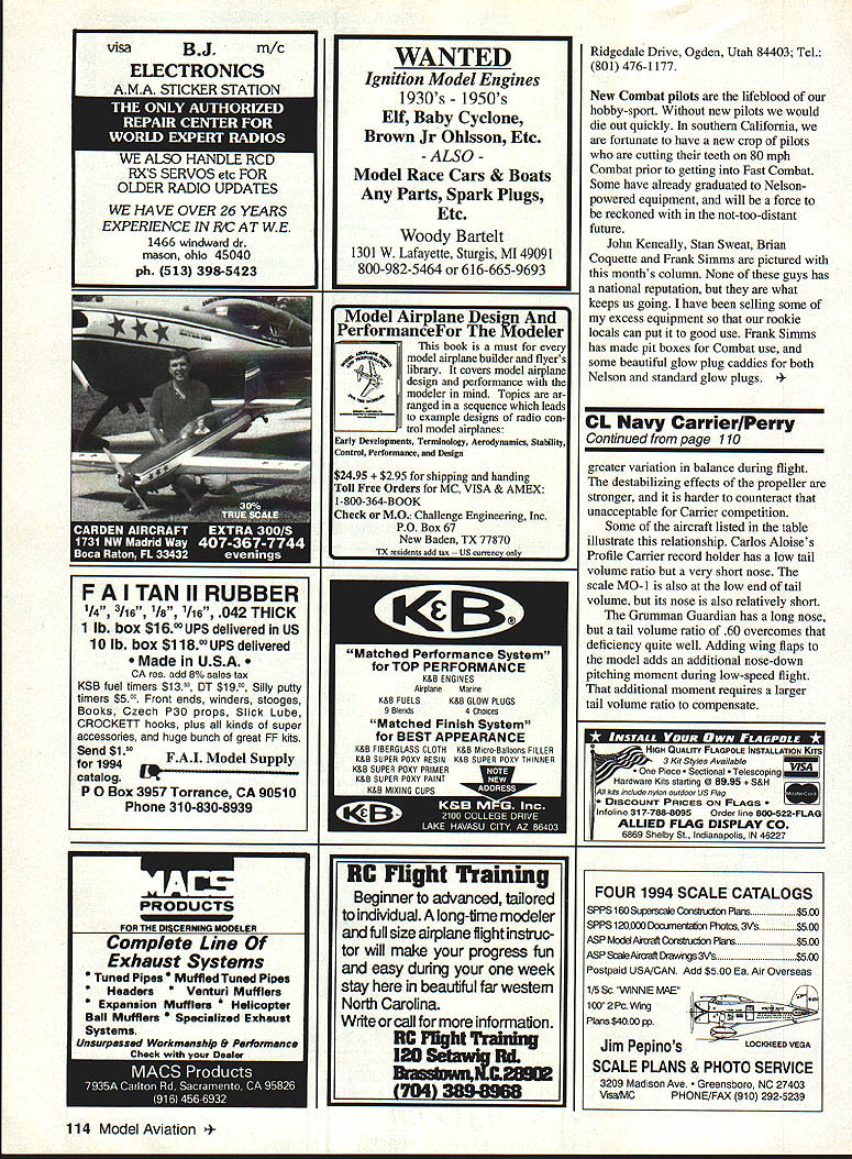
Tail Volume Ratio formula
Vt = (St × lt) / (Sw × MACw)
Where:
- Vt = tail volume ratio
- St = tail area
- lt = tail moment arm
- Sw = wing area
- MACw = mean aerodynamic chord (wing)
The wing and tail areas in this equation are self-explanatory. The only "trick" is to include the wing and tail area that is inside the fuselage. Simply extend the leading and trailing edges to the centerline of the fuselage, ignoring any small changes in outline which occur near the fuselage (such as wing fairings or landing gear fairings).
The tail moment arm is the distance between the quarter-chord points of the wing MAC and the tail MAC. The quarter-chord point is the point that lies 25% of the distance from the leading edge to the trailing edge at the MAC.
The mean aerodynamic chord (MAC) is a theoretical wing chord that represents the characteristics of the entire wing. Approximate methods for finding MAC:
- For a rectangular (non-tapered) wing, the MAC is simply the wing chord (leading edge to trailing edge distance measured parallel to the direction of flight).
- For a tapered wing, the MAC divides the wing into two equal areas and is inboard of the "average" chord. For most tapered wings, the MAC falls at about 43% of the centerline-to-tip distance. On elliptical wings the MAC falls at about 42.4% of the centerline-to-tip distance.
I will discuss the exact methods for computing MAC in my next column.
Carrier Model Selection
Many years ago I devoted a column to selecting a prototype upon which to base a CL Navy Carrier model. Since then, our style of flying and the types of models have changed considerably as modelers learned how to gain optimum scores under the current scoring system. I've received a number of calls since the Nationals from Carrier modelers seeking alternatives to the MO-1. Those calls, combined with the realization that some original ideas about what makes a good Carrier model are no longer appropriate, have prompted me to update the information and repeat the subject.
Other things being equal, the relative simplicity of the MO-1 design and the experience gained by modelers using it make it a good starting point. However, there are no strong reasons to select the MO-1 over other prototypes that meet the size, aspect-ratio, and tail-volume criteria discussed below. In fact, there is one good reason not to select the MO-1: its fuselage is small.
A smaller fuselage offers less drag than a larger one, but in our models there are other factors that overshadow fuselage drag. The engine, lines, landing gear, and hook are fixed drag producers. Other than hiding them inside other parts of the model, there isn't much we can do about the drag they produce. Fuselage drag is small by comparison. A larger fuselage conceals more of the engine and control systems, and thus compensates for increased fuselage drag by reducing engine and system drag. Control systems, engine mounts, and fuel tanks are all easier to fit into larger fuselages. A fuselage with a large cross section can be built lighter than a small fuselage and still retain the same strength.
With its fixed width, the fuselage of a Profile Carrier model is a different story; a smaller fuselage is lighter.
There are two ways to improve scores in CL Navy Carrier:
- Go faster during high speed.
- Go slower during low speed.
Today's models are slower than those flown before the scoring change. Since engine technology hasn't declined over the last 15 to 20 years and line sizes are the same, the reason must lie in our models. The three major contributors are:
- Models are bigger (more drag).
- Models are heavier (slower acceleration).
- External lines and line guides add drag.
Unfortunately, there is little we can do about some of these factors. We need larger models for the overall scoring advantage we get from improved low-speed performance. There are a few prototypes in which lines can be enclosed in the wing and still obtain adequate line sweep for reliable low-speed flight. Weight can be kept near the old standards for Class I and II models, but doing so takes effort. As always, speed is primarily a factor of power, with limited contribution from the design of the prototype.
On the low-speed end, the factors that were important 20 years ago are no longer the only important ones. Low-speed scores are primarily a function of wing loading: lighter wing loading produces better low-speed scores. Because the weights for many of a model's components are fixed, the way to reduce wing loading is to increase wing area. Wing flaps were very common on older models, but have lost importance under the present method of flying in a full stall. Models without flaps are lighter and easier to build.
Since we no longer need to worry about complex flap configurations, there are more options. Because the primary low-speed design consideration is size, a good place to start in selecting a design is by deciding what wing area to use. For good low-speed performance, a model should have at least 300 square inches of wing area. Few eligible prototypes cannot meet that criterion.
- A few designs, like the Supermarine 322 and some twin-engine patrol aircraft, are at about 250 square inches or less at a 44-inch span and are not very practical for Carrier competition.
- The Lockheed U-2 is legal but manages only 135 square inches at 44 inches span and is impractical for Carrier competition.
- The Grumman Guardian and Fairey Barracuda are just under 300 square inches at a 44-inch span and represent extremes in aspect ratio among acceptable candidates.
- Other prototypes go to a maximum of a little more than 440 square inches (Vought OS2U Kingfisher).
I prefer 350 to 375 square inches of wing area because I believe it produces the best low speed without sacrificing high-speed performance. The MO-1 at a 44-inch span is about 375 square inches, which is why it has been successful—but many other prototypes will fit this criterion. What is necessary is an aspect ratio of 5.5 or lower.
Aspect ratio is a measure of how "skinny" a wing is. It is defined as the wingspan squared divided by the wing area. The table above includes aspect ratio data for comparison.
The other factor in acceptable low-speed performance is aircraft control. If the model can't be reliably held in a stall, low-speed scores will suffer. The measure of control effectiveness for this purpose is tail volume ratio. A larger tail volume ratio produces more effective pitch control and is more tolerant to changes in balance point. In other words, models with larger tail volume ratios retain acceptable flight characteristics over a broader range of balance points.
The smallest acceptable tail volume ratio is about .35. There are few propeller-driven prototypes with lower tail volume ratios; only jet-powered aircraft tend to have smaller ratios. The key to acceptable handling qualities lies in avoiding prototypes that have both small tail volume ratios and long noses (propellers mounted well forward of the balance point). Those tend to require more ballast in the tail and are likely to have fuel (a variable weight) farther forward, causing trim changes as fuel is used. These trim changes are difficult to anticipate and control.
Wing planform and airfoil also influence low-speed behavior. Elliptical and tapered wings are acceptable, but simplicity of construction and predictable stall characteristics favor straight-taper or simple trapezoidal wings. Very thin, high-aspect-ratio wings tend to give poorer low-speed performance.
A semispan or all-moving stabilizer is unnecessary; a well-sized fixed stabilizer with an appropriately sized elevator and good hinge moments is adequate.
Some aircraft illustrate the relationship between tail volume ratio and nose length. Carlos Aloise's Profile Carrier record holder has a low tail-volume ratio but a very short nose. The scale MO-1 is also at the low end of tail volume but has a relatively short nose. The Grumman Guardian has a long nose, but a tail-volume ratio of .60 overcomes that deficiency. Adding wing flaps to a model adds an additional nose-down pitching moment during low-speed flight; that additional moment requires a larger tail-volume ratio to compensate.
The formula for computing tail volume ratio (Vt) is shown earlier in this column.
In the next column, I'll discuss the effects of design configuration on neutral point and give some guidelines on balancing Carrier models for both high- and low-speed handling qualities.
Transcribed from original scans by AI. Minor OCR errors may remain.

