
CONTROL LINE NAVY CARRIER
Dick Perry 31010 East Sunset Drive North Redlands, CA 92373-7453
This month's offerings
- Discussion on balance points for Carrier models, with supporting theory.
- A computerized scoring program from Melvin Schuette.
NATS Special Events
As I announced in my last column, the Navy Carrier Society will sponsor Sportsman Profile Carrier on the Saturday following regular CL Navy Carrier competition flying at the National Aeromodeling Championships (NATS). On the same day, the Dallas-area carrier modelers will sponsor a .15 Carrier event. When this was written (early April), there was not yet a sponsor for Skyray Carrier. The Navy Carrier Society newsletter will contain the latest information on NATS Carrier activities. Thanks to Bill Bischoff and the rest of the Dallas carrier gang for offering to host .15 Carrier.
Carrier model selection
In my last column I promised to discuss the balancing of Carrier models to ensure acceptable handling qualities in both high- and low-speed flight. Little has been written about the technical aspects of this subject in the modeling magazines, and what has been written has sometimes generated controversy.
Having been on the receiving end of some of those discussions in the past, I'm now embarking on the potentially hazardous course of including technical information in this column. Lest the purists jump too hastily to their typewriters, let me point out that my intent is to provide simplified, condensed (and therefore not academically rigorous or 100% accurate) information that might be useful to readers.
The size and location of the horizontal tail are important in determining how well a model can be controlled in low-speed flight (and high-speed flight as well). A larger tail area located farther from the balance point is more effective than a smaller, closer horizontal tail.
One of the other significant factors in the tail volume ratio equation is the length of the Mean Aerodynamic Chord (MAC) of the wing. As the MAC increases, tail volume ratio (and control effectiveness) decreases if all other factors remain the same. The MAC is a primary dimension used in stability and control determinations for both models and full-scale aircraft. It represents the entire wing's aerodynamic characteristics as a single airfoil with fixed dimensions and location.
Positioning the balance point of a model logically involves locating it in relation to the wing. Because the MAC represents the entire wing, we need to accurately determine the MAC to accurately and consistently position the balance point of the model.
Quick skip
If you prefer to skip the theory and get right to the practical recommendations, you can skip the next few paragraphs. If you are interested in the reasons behind the recommendations, or if you want to complain about my butchering of the "pure" technical aspects, read on.
Stability and control — the basics
For an aircraft to fly straight and level, all forces acting on it must balance. The same goes for all torques or twisting moments those forces produce. If the forces and moments don't balance, the aircraft will change its direction of motion or its attitude (usually both). In control line flying we are primarily concerned about pitch, because the force of the lines provides stability in roll and yaw despite the aerodynamic forces.
For level flight, the total upward force (lift on wing and tail, primarily) must balance the total downward force (weight, plus an additional contribution from the lines whenever flying height is higher than the control handle). Weight effects act at the balance point of the model. The lift of the wing and tail act through a point located 25% aft of the leading edge of the MAC.
On a conventional aircraft (tail behind the wing) there are two possible force configurations:
- The balance point can be in front of the center of lift of the wing (25% MAC).
- Or the balance point can be behind the center of wing lift.
Control line models most often balance in front of the wing center of lift. This configuration requires a downward force on the tail to keep the model balanced in pitch. The downward tail force requires a corresponding increase in wing lift to keep the forces balanced vertically.
Free-flight models often use a balance point aft of the wing center of lift so that the tail can contribute to total lift and thus increase glide performance. Both configurations can be stable.
Another factor in stability and control is static stability. We want our aircraft to fly hands-off—to keep going in the intended direction until we make a control input.
- Positive static stability: the aircraft returns to its initial flight condition if disturbed. This is desirable.
- Negative static stability: small changes in attitude or control forces cause the aircraft to diverge further from the original condition. This is undesirable and can be extreme enough to make a model try to turn around and fly backwards.
When the nose of an aircraft pitches up unintentionally (from turbulence or other causes), lift on the wing and tail changes—both increase. If the tail is pushing down (because the balance point is forward), then the tail's downward force will decrease or may even change to an upward force.
Both wing and tail experience approximately the same change in lift coefficient. The change in actual lift for each surface is proportional to the change in lift coefficient (the same for both wing and tail) times the area of each surface. If the balance point is forward of the center of lift, the increase in lift caused by both wing and tail will tend to lift the tail and return the model to level flight.
In a conventional airplane with positive static stability the balance point can be behind the wing center of lift. In this case, the increase in wing lift tends to increase the pitch attitude even further. The pitching moment is the product of the increase in lift times the distance from the wing center of lift to the balance point.
The increase in the tail's lift can overcome this because the tail is farther from the balance point, and its moment (lift times distance to the balance point) is greater than the moment caused by the wing.
As the balance point moves aft it will reach a position where the pitch-up moment caused by the wing and the pitch-down moment caused by the tail balance each other. This point is called the neutral point. It is the boundary between positive and negative stability.
The key term is static margin: the distance (usually expressed as a percentage of the MAC) between the balance point and the neutral point. The greater the static margin, the more stable the model will be, and the more the elevators will have to work to overcome this stability to make the model maneuver.
For good handling qualities, we need positive static stability—the model must balance forward of the neutral point. As static margin increases, elevator control becomes less effective.
To achieve good high-speed handling qualities as well as effective low-speed elevator control, a compromise is necessary. By experience, this compromise places the balance point about 30% of the MAC forward of the neutral point (static margin = 30% MAC). This static margin is large compared to full-scale aircraft. One reason is that the propeller (if mounted in front) tends to make the aircraft unstable. More powerful engines and longer noses increase the effect. Compared to full-scale aircraft engines, our model engines are much more powerful, so our models require larger static margins to compensate.
Making it work — practical steps
The first step is to determine the MAC of the wing and the horizontal tail.
- For a rectangular wing, the MAC is the chord. If the rectangular wing is swept, place the MAC at half the distance from the centerline to the tip.
- Tapered wings require more calculation. For rough estimates, the approximations in my last column will suffice. For stricter accuracy, the MAC lies on the centroid of the wing platform (for half of the wing—centerline to tip).
If you want to avoid the math, draw the wing half on cardboard, cut it out, and find the centroid (balance point) of the cardboard. Assume the MAC is the chord that places the centroid of that rectangle the same distance from the leading edge as the centroid of the wing half. Remember that for these purposes the wing outline extends into the fuselage all the way to the centerline.
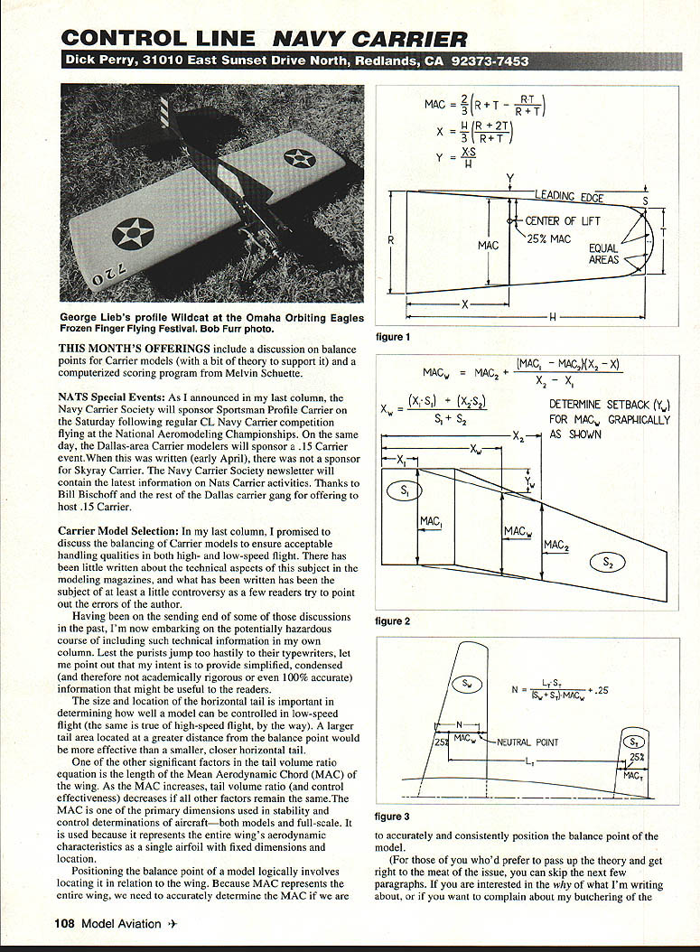
Determining the MAC for a tapered wing (reference to Figure 1)
Tapered wings present some challenge. For tapered wings use an equivalent rectangular platform defined by root and tip chords.
- If the wingtip is not a convenient square tip, approximate the tip chord for the equations by drawing a theoretical square wingtip at a point where the outboard tip area would fill in the vacant inboard areas. Extend the leading and trailing edges to this theoretical tip position and use that outline as the equivalent platform.
- Note: for a delta wing the tip chord is zero.
Terms used in the Figure 1 method:
- R = Root chord
- T = Tip chord
- H = Half span
- X = Spanwise location of MAC
- S = Setback of tip chord (sweep at the tip)
- Y = Setback of MAC
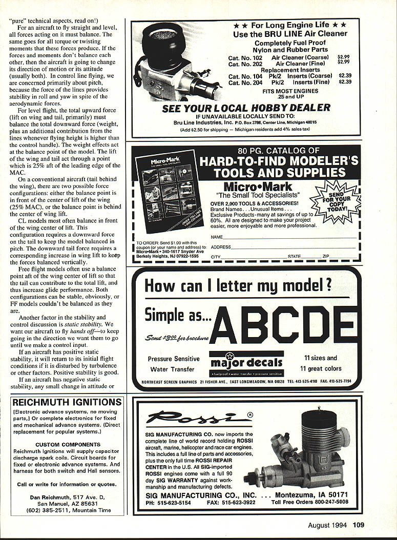
If your model's wing consists of two sections (as on the MO-1), you can calculate the MAC for each section and combine them to get the MAC for the entire wing. The method is shown in Figure 2.
Terms used in the Figure 2 method:
- X = Spanwise location of MACs
- S = Area of wing segments
- Subscripts 1 and 2 refer to inboard and outboard segments; W refers to the entire wing.
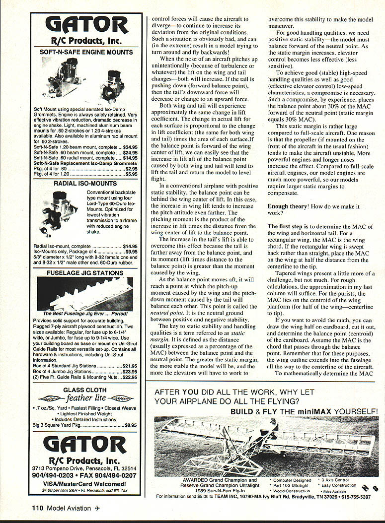
Determining the neutral point (reference to Figure 3)
Once you have determined the MAC for wing and tail, the neutral point is determined using the method in Figure 3. Most terms are self-explanatory. The tail moment arm (LT) used for the calculations is the distance between the 25% MAC points of the wing and the tail.
The result of the calculation is a decimal (convertible to percent) that represents the distance from the leading edge of the MAC to the neutral point. This distance as a percent of MAC will be valid for any size model of the same configuration.
I've listed approximate neutral points for the same aircraft that appeared in my last column. Notice the neutral points are almost all behind the midpoint of the MAC.
Recommended static margin and adjustments
- For good flying qualities, the balance point of a CL Navy Carrier model should be about 30% MAC forward of the neutral point (static margin = 30% MAC).
- If the fuel tank is forward of the balance point, adjust the balance to account for the fuel you expect to have in the tank at the end of the flight.
- The 30% figure should produce a model that handles reasonably well. Fine tuning will require test flying, but 30% is a good starting point.
Examples:
- Carlos Aloise's Profile Carrier: static margin 33% MAC.
- Bill Bischoff's Sniper: static margin 28% MAC.
- My MO-1s: about 28% MAC.
- Tom Schaefer's Kingfisher: 32% static margin.
All critical dimensions relate directly to the MAC and are measured aft from the MAC leading edge. The location of the MAC in relation to the rest of the aircraft is critical to accurately determining neutral point, balance point, etc. The leading edge of the MAC is unlikely to correspond to the leading edge of the root chord.
Balance point becomes less critical for models with large tail volume ratios. Therefore, a large tail volume ratio is appropriate for models that have large fuel tanks mounted forward of the balance point.
That's it for this month. I hope to see many of you in Lubbock. Keep your hook dry!
Transcribed from original scans by AI. Minor OCR errors may remain.

