
CONTROL LINE: NAVY CARRIER
Author
Dick Perry, 7005 Del Oso Court NE, Albuquerque NM 87109-2930
Contests and rules update
As this column is being written (early February) the Control Line Contest Board (CLCB) is preparing for a vote on the urgent proposal to restore the two-minute starting time allowance for multi-engine models. (Editor's note: Steve Kaluf, AMA Technical Director, has confirmed that the proposal passed and is effective immediately.)
Two basic proposals for the 1999 rules cycle were scheduled for a February 28 vote. You should expect the results in the Model Aviation you receive in June. Proposals that pass the initial vote will be subject to cross-proposals, which must be submitted by July 15.
It is unfortunate that the schedule does not allow for discussion of cross-proposals at the National Aeromodeling Championships (Nats); perhaps an extension can be agreed upon in the Executive Council. Whatever the schedule, if you want to participate in the cross-proposal discussions and deliberations, contact Pete Mazur at 5 Windsor Court, Aurora IL 60504; (630) 466-4051. Pete chairs the Navy Carrier Advisory Committee to the CLCB.
I expect Navy Carrier proposals to be discussed at the annual Navy Carrier Society (NCS) banquet Friday, July 18, which will be held in conjunction with the Nats; the banquet is the venue for recognizing the Navy Carrier winners.
NCS awards
As in the past, the NCS will present awards:
- Eugene Ely Award: Goes to the Navy Carrier national champion — the modeler who amasses the greatest total score for all official Nats Navy Carrier events (Skyray, Sportsman, and Nostalgia).
- Rookie of the Year: Selected from the modelers who compete in their first Nats Navy Carrier events.
- Carol Johnson Spirit of Volunteerism Award: Presented to the person whose unselfish contribution to Navy Carrier helps the rest of us enjoy the events.
I discussed the Nats schedule in my previous column. Sig will sponsor the Skyray Carrier event again this year, the NCS will sponsor Sportsman Carrier, and the new Nostalgia Carrier event will be on Saturday. At this time, the .15 Carrier event has no sponsor; watch the NCS newsletter for information on whether or not it will be flown.
Nostalgia Carrier
The purpose of Nostalgia Carrier is to keep alive the memories of the earlier Carrier-flying days, which predated the current prop-hanging style of slow flight. The event is for models that were published or kitted prior to January 1, 1976. It will be flown according to 1974–75 Carrier rules (with a few minor exceptions).
Since this is the first year for Nostalgia Carrier, Class I and Class II will be combined, with a 5% handicap in total score for the smaller Class I models. Also, non-Schnuerle engines will receive a 20-point bonus. Complete rules will be sent to anyone who sends me a request with a self-addressed stamped envelope.
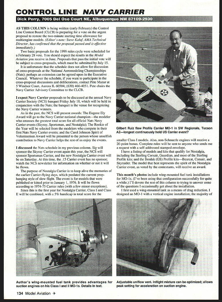
I have a listing of models and kits that qualify for Nostalgia, including the Sterling Corsair, Guardian, and most of the Sterling Profile kits; and the Brodak (GS) Profile kits — Bearcat, Corsair, and Skyraider. The model that best represents the spirit of the Nostalgia Carrier event, as voted by the contestants, will receive an award.
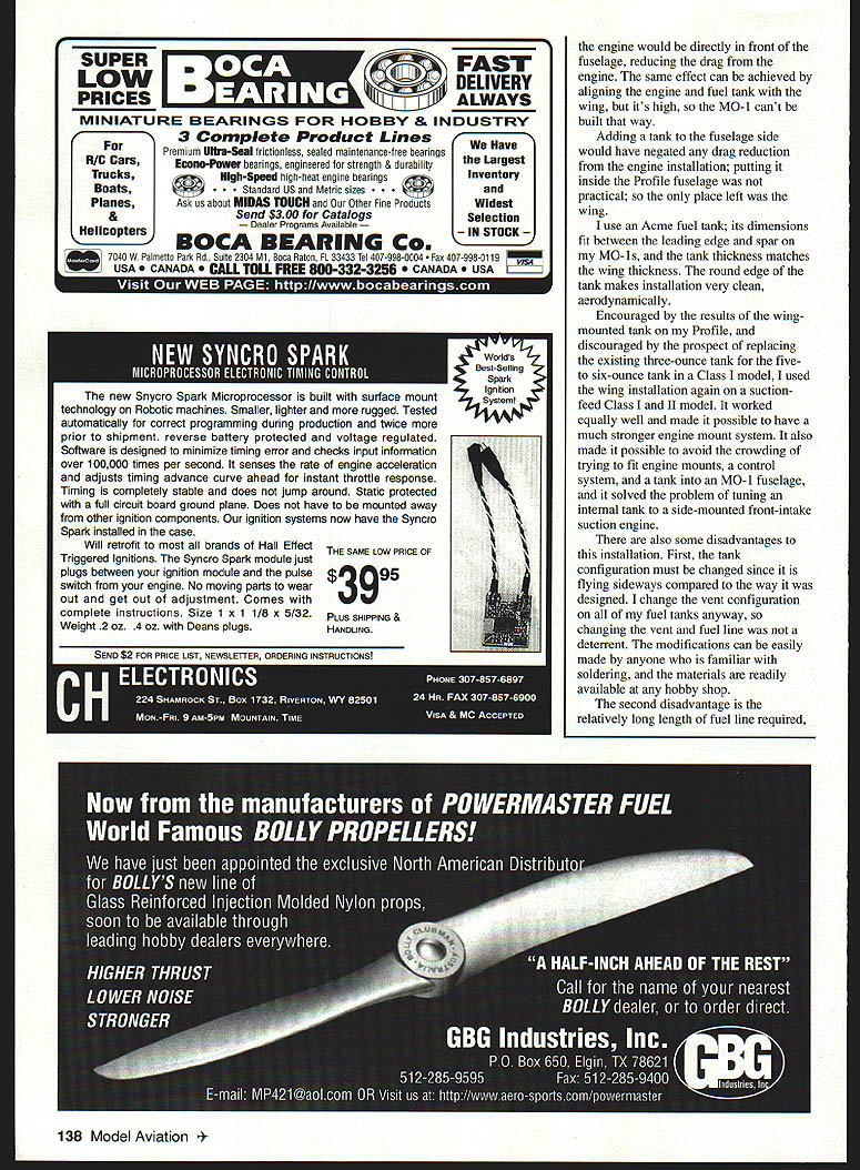
Wing-mounted fuel tank installation for MO-1s
This month's photos include wing-mounted fuel tank installations for MO-1s. (I've been using that configuration successfully for quite a while.) I'll devote the rest of this column to trying to answer some of the questions I occasionally get about the installation.
I first used a wing-mounted tank as a means of drag reduction. I designed an MO-1 with a vertical engine installation; the majority of the engine would be directly in front of the fuselage, reducing the drag from the engine. The same effect can be achieved by aligning the engine and fuel tank with the wing, but it’s high, so the MO-1 can’t be built that way.
Adding a tank to the fuselage side would have negated any drag reduction from the engine installation; putting it inside the Profile fuselage was not practical; so the only place left was the wing.
I use an Ace fuel tank; its dimensions fit between the leading edge and spar on my MO-1s, and the tank thickness matches the wing thickness. The round edge of the tank makes installation very clean, aerodynamically.
Encouraged by the results of the wing-mounted tank on my Profile, and discouraged by the prospect of replacing the existing three-ounce tank with a five- to six-ounce tank in a Class I model, I used the wing installation again on a suction-feeding Class II MO-1. It worked equally well and made it possible to have a much stronger engine mount system. It also made it possible to avoid the crowding of trying to fit engine mounts, a control system, and a tank into an MO-1 fuselage, and it solved the problem of tuning an internal tank to a side-mounted front-intake suction engine.
There are also some disadvantages to this installation. First, the tank configuration must be changed since it is flying sideways compared to the way it was designed. I change the vent configuration on all of my fuel tanks anyway, so changing the vent and fuel line was not a deterrent. The modifications can be easily made by anyone who is familiar with soldering, and the materials are readily available at any hobby shop. The second disadvantage is the relatively long length of fuel line required, compared to a typical Profile installation in which the tank is immediately behind the engine. The high mounting compensates on the ground and the combination of vent location and needle valve setting compensate during takeoff and in flight.
Vent tuning and adjustment
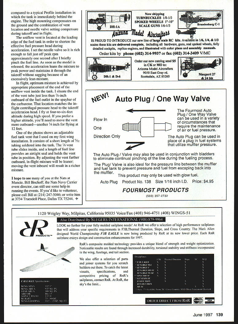
The uniflow vent is located at the leading edge of the fuel tank in order to shorten the effective fuel pressure head during acceleration. I set the needle valve so it is rich enough to fall just off peak approximately one second after I briefly pinch the fuel line. As soon as the model is released, the acceleration leans the mixture to peak power and maintains it through the takeoff without sagging because of an excessively lean mixture.
In flight, optimum mixture is achieved by appropriate placement of the end of the uniflow vent inside the tank. I situate the end of the vent tube just less than 1/4-inch outboard of the fuel outlet in the spraybar of the carburetor. That location matches the inflight centrifugal pressure head to the takeoff acceleration head. I fly at four-to-six-feet altitude during high speed. If you prefer a higher altitude, you'll need to move the vent more outboard — another 1/4 inch for flying at 12 feet.
One of the photos shows an adjustable fuel tank vent that I used on my first wing installation. It consists of a short length of 5/32 tubing soldered into the tank. The 1/8 vent tube slides inside, and a length of fuel line provides an airtight seal and holds the vent tube in position. By adjusting the vent farther outboard, in-flight mixture will be leaner; moving the vent inboard will result in a richer mixture.
Volunteer information
I hope to see many of you at the Nats at Muncie. Bill Bischoff, the Nats Navy Carrier event director, can still use some help in running the events. If you'd like to volunteer, please call Bill at (214) 247-5046; or write him at 3734 Truesdell Place, Dallas TX 75244.
Transcribed from original scans by AI. Minor OCR errors may remain.

