
Control Line: Navy Carrier
Richard Perry
I RECEIVE letters occasionally from people inquiring about whether this or that aircraft would make a good subject for a scale Carrier model. Now that we can receive scale bonus points in Profile Carrier as well, the subject has even broader application. Since the rules changed a few years ago, jet prototypes have held some interest, too—converted to props for our purposes, of course.
There are many aspects to consider in selecting a subject for a Carrier model. Much of these concern ease of construction and personal preference regarding flaps, ailerons, etc. and the complexity of mechanisms for operating these. I will discuss two items this month: size and tail volume ratio. Many of the questions and comments I hear center around these two areas.
My personal preference for model size is on the larger side. Class I should be 140-160 sq. in. total wing area (including that in the fuselage), and Class II should be 200-225 sq. in. Some people build smaller models to reduce drag and improve high speed. These models can be slightly lighter, but much of the weight of a Carrier model is fixed (engine, fuel, gear, control system, etc.).
The smaller model would have less drag in proportion to its wing area if it were an exact copy of the original, but it isn't. The smaller model exposes more of the engine, and the engine provides a significant amount of drag. Since the lines we fly on account for at least 2/3 of the total drag, and other factors, such as engine and gear, are also fixed, one can see the small effect that model size has on top speed. Yet wing area can have a significant effect on slow speed and the ease with which a model flies. Wing area is purely a factor of the scale to which a model is built, but fuselage size, once wing area has been determined, depends on the proportions of the full-scale aircraft. A small fuselage cross section does not necessarily mean less drag. A small fuselage exposes more of the engine. and thus may even increase drag. For me, the most important thing to consider regarding fuselage size is that it be large enough to hold easily all of the equipment that goes into the model. A large fuselage can be built to the same weight as a smaller one and actually be stronger.
To summarize the last few paragraphs: build the model large enough to fly well, and choose a subject that has a fuselage big enough to make equipment installation easy. My next Class II, by the way, will have a fuselage 6 inches deep and 4 1/4 inches wide. In Profile Carrier, of course, the fuselage just holds the engine, wing, and tail together with everything hanging out in the breeze, so small fuselage dimensions are desirable to reduce weight.
The most critical factor in selecting a scale subject, or in designing a non-scale Profile Carrier model, is the size and location of the horizontal tail. The tail must be able to generate enough moment to stall the wing. This can be done with a smaller tail a long distance from the wing or by a larger tail set close to the wing.
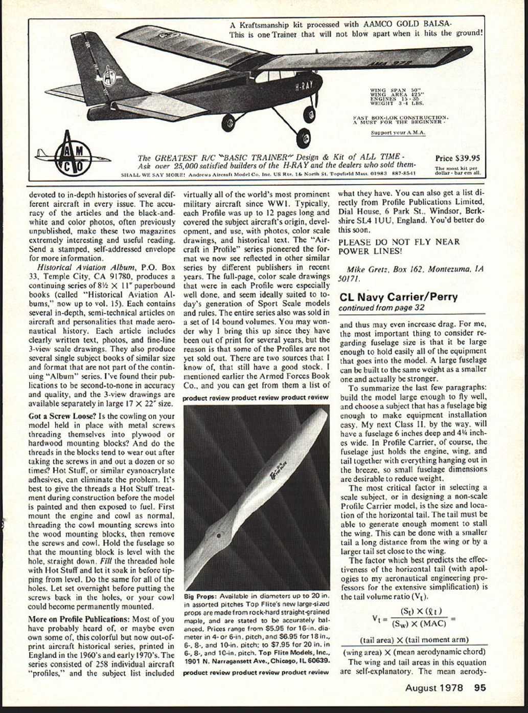
The factor which best predicts the effectiveness of the horizontal tail (with apologies to my aeronautical engineering professors for the extensive simplification) is the tail volume ratio (Vt).
Vt = (St x lt) / (Sw x (MAC))
(tail area) x (tail moment arm) (wing area) x (mean aerodynamic chord)
The wing and tail areas in this equation are self-explanatory. The mean aerodynamic chord (MAC) on a non-tapered wing is simply the wing chord (leading edge to trailing edge distance). For a tapered wing, the MAC is located inboard of the mean chord (chord measured at half the distance to the wing tip from the fuselage centerline). For most tapered wings, measure the MAC at about 45% of the distance from the fuselage centerline to the wing tip. On a pure delta, measure the MAC at 33% of the fuselage-tip distance.
The tail moment arm is measured between the quarter-chord points of the wing and tail. The quarter-chord point is the point 25% back from the leading edge at the MAC for each surface.
The larger the tail volume ratio, the more effective will be the tail. Some sample ratios are:
Aircraft Vt AF2S Guardian .59 A1H Skyraider .53 Short Seamew .49 MO-1 .41 AM-1 Mauler .40 A-7 Corsair II .33 F-4 Phantom II .26
Note that most higher-powered propeller aircraft have tail volume ratios exceeding .45. An MO-1 model at Vt = .41 can be stalled, but it doesn't have flaps. Flaps force the nose down and require a larger tail moment to compensate. The balance point of a Mauler with flaps would be more critical than on a model with a larger tail volume ratio.
Any Carrier model with normal (about half span) flaps should have good handling qualities if it has a tail volume ratio over .45 and balances at 10-20% MAC. Without flaps, Vt = .40 is adequate. Profile models, because of their lower power and larger wings, can get by with Vt = .30 and a balance point at 25% MAC without developing undesirable handling qualities at high speeds.
I threw in the A-7 and F-4 to demonstrate that most jets have tails that are too small to make them good Carrier subjects with a prop for power. Without a prop in the nose, the jets don't need a large tail volume for stability, yet we Carrier modelers don't have jets as workable propulsion systems just yet. Most jets have the engines toward the aft end and usually have long noses to balance the aircraft. When we put a heavy engine in the nose, balance becomes a problem.
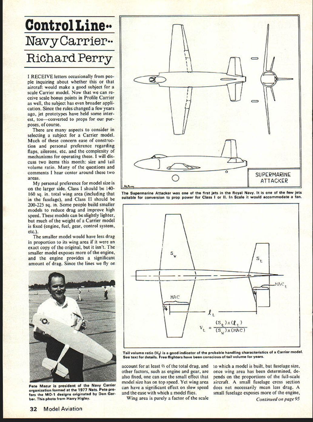
A happy exception to the norm for jet carrier aircraft is the Supermarine Attacker (see drawing). Developed in the mid 1940's, it resembles the conventional prop fighters of that time period much more than later jets. The tail is quite large, and the nose is relatively short. The wings are straight, and it even has a conventional tail-wheel landing gear.
For those of you who may be tempted, note that the fuselage is circular from the inlet to the tail. A mold (for fiberglass or balsa shell) or even the fuselage itself could be turned on a lathe.
I am doing some work on throttles right now that I hope to be able to report on in my next column. If there are any subjects which you would particularly like to see in this column, drop me a line.
Richard L. Perry, 5016 Angelita Ave., Dayton, OH 45424
Transcribed from original scans by AI. Minor OCR errors may remain.

