
Control Line: Navy Carrier
Richard Perry
The subject this month is new Carrier fliers. I'm starting a series to cover some of the more basic aspects of our events, trying to pass on hints to help the newcomer become familiar with the building and flying techniques that make Navy Carrier unique among control-line events.
Profile Carrier Engine Rules
The Profile Carrier event was originated as a stepping-stone type event to provide an easier transition to scale Carrier flying. The major emphasis was on equipment availability, with low relative cost also important. Control systems were limited so that the commercial three-line system was the best to use. Model specifications were written to make use of the wide variety of .35-sized profile kits on the market. The engine rules were set up around engines that were relatively inexpensive and that could be found on almost any dealer's shelf.
The original rules have changed little as far as controls and models are concerned, and the supply of commercial control systems and suitable kits is at least as good, and probably better, than it was ten years ago. Engine rules have been less stable, however, with changes attempting to satisfy two opposing points of view: the "keep it simple" philosophy and the "don't fight progress" side.
- The "keep it simple" followers want relatively inexpensive, commercially available equipment to remain competitive, as it was before the advent of plain-bearing conversions and limited-run specialty engines.
- The "don't fight progress" group feels that earlier restrictions were too limiting and prevented the event from developing.
What has developed is a controversy over the old rules in spite of general agreement with the original goals of having commercially available, competitive engines. The problem, as I see it, is that the original goals cannot be met with the original rules.
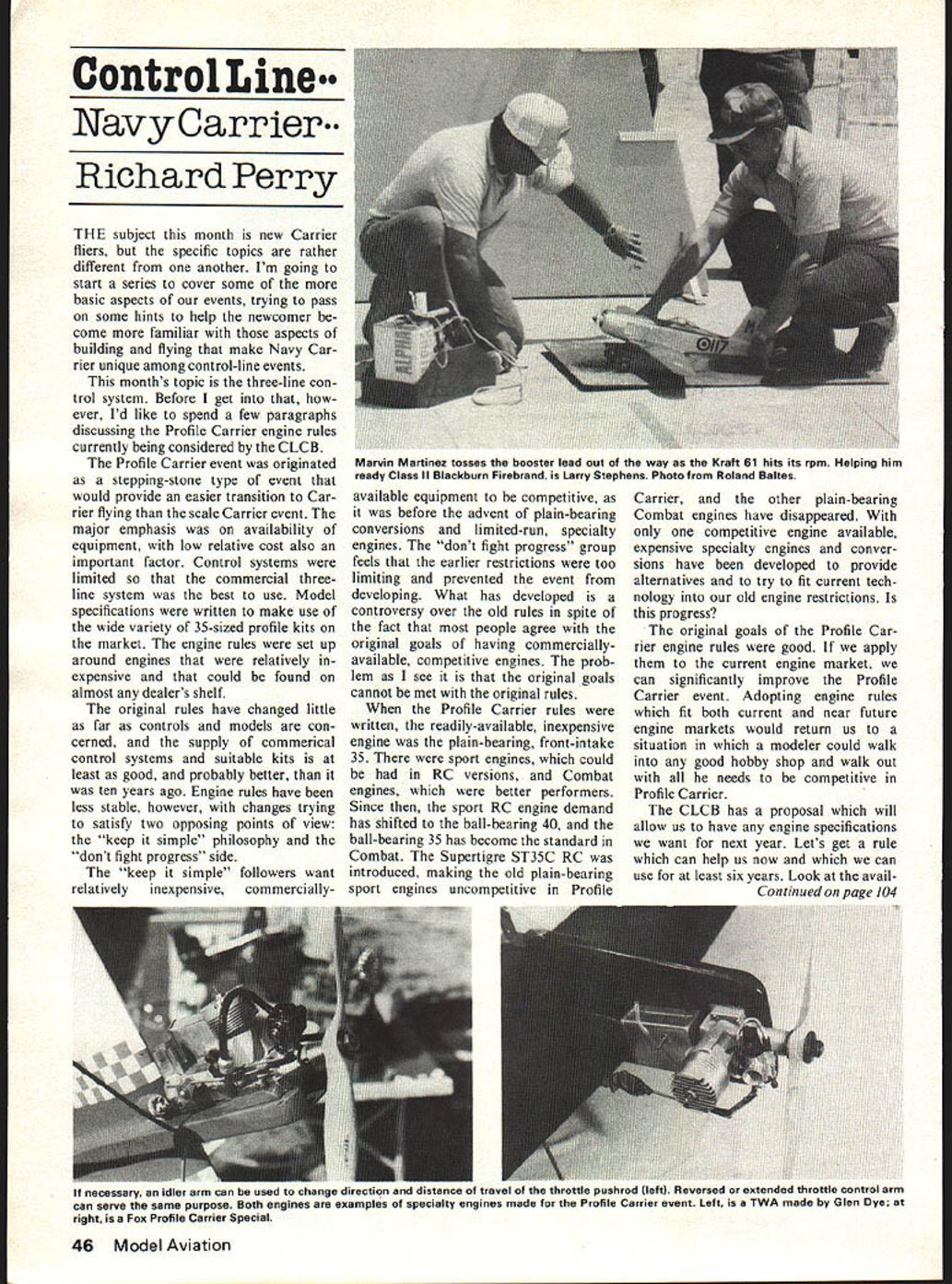
When the Profile Carrier rules were written, the readily available, inexpensive engine was the plain-bearing, front-intake .35. There were sport engines available in RC versions, and Combat engines that were better performers. Since then demand has shifted to the ball-bearing .40 for sport RC, and the ball-bearing .35 has become the standard in Combat. The Supertigre ST35C RC was introduced, making the old plain-bearing sport engines uncompetitive in Profile Carrier, and the other plain-bearing Combat engines have disappeared. With only one competitive engine available, expensive specialty engines and conversions have been developed to provide alternatives and to try to fit current technology into our old engine restrictions.
The original goals of the Profile Carrier engine rules were sound. If we apply them to the current engine market, we can significantly improve the event. Adopting engine rules that fit both current and near-future engine markets would return us to a situation in which a modeler could walk into any good hobby shop and walk out with everything needed to be competitive in Profile Carrier.
The CLCB has a proposal that will allow us to adopt new engine specifications for next year. Let's get a rule that can help us now and that will be usable for at least six years. We should assess the availability of good plain-bearing .35s, ball-bearing .35s and .40s, and available throttles, then decide where to direct our efforts in Profile Carrier.
Three-Line Control Systems
The universally accepted standard for the Navy Carrier event is the three-line control system. It is important for newcomers to understand the basics of these systems and the details unique to Carrier flying.
Commercial Units
There are two commercial three-line units available:
- G-S Products
- Sturdibuilt
Both units work on the same principle: the three lines carry a balanced load and throttle control is achieved by moving the third (throttle) line in relation to the elevator (elevation) lines via a throttle control lever at the top of the handle. Either brand of handle will work with either control unit, but the G-S Products system offers greater smoothness, range of operation, and strength.
Bellcrank Configurations
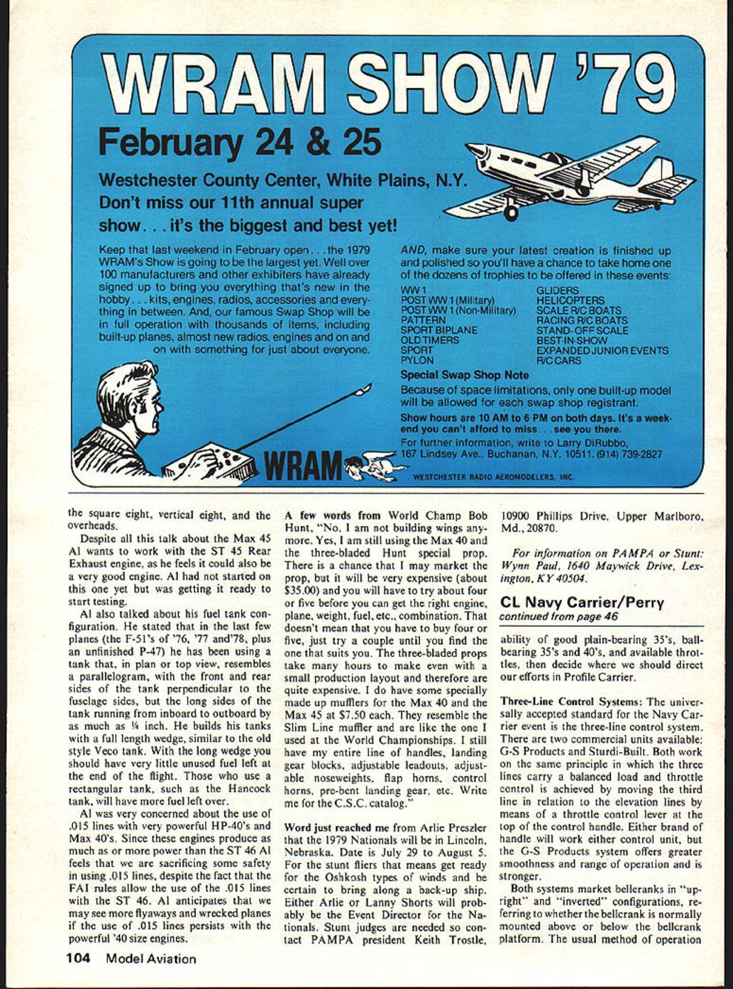
Both systems market bellcranks in "upright" and "inverted" configurations, referring to whether the bellcrank is mounted above or below the bellcrank platform. The usual method of operation is to mount the bellcrank in the inverted position and use an idler arm to change direction and distance of travel of the throttle pushrod. The reversed control arm can serve the same purpose.
The normal method is to use a rearward pull of the throttle lever on the handle to open the throttle. With the plane unit mounted as intended, this results in a rearward pull on the throttle pushrod.
Throttle Motion and Reversing
If the direction of motion is incorrect for opening the throttle on a particular engine, you have several options to reverse travel:
- Mount the plane unit upside down (i.e., use an upright bellcrank mounted under the platform) to reverse the direction of travel.
- Use an intermediate bellcrank or idler arm between the plane unit and the engine.
- Mount an additional control arm on the throttle opposite the normal control arm.
Control Installation and Binding
A very important part of the control installation is checking to ensure that throttle movement and elevator control are free of any binding. This check should be accomplished while the bellcrank is still accessible and with the engine installed. Failure to correct binding in the control system can result in erratic control of engine or elevator during low-speed flight.
The rules require that the throttle line exit the model between the elevator control lines. This is a good idea anyway because it helps keep yaw trim on the model consistent.
Leadouts and Line Lengths
When installing the leadouts, it is best to have the throttle leadout longer than the elevator leadouts so there will be less chance of interference between the line connectors. To allow the use of equal-length control lines, the throttle leadout should be 3 3/4" longer than the elevator leadouts measured when the throttle leadout is fully extended.
When making control line sets for Carrier models, there are a few areas that require special attention because they are unique to Carrier and three-line control systems. Unlike the racing and combat events, line length requirements for Carrier are 60' minimum to 60'6" maximum (not 60' ± 6"). Because of the close tolerance, ready-to-use lines may not be properly sized unless the leadouts are cut to match a specific set of lines. Variations between line sets can cause trouble, so I prefer to avoid potential problems and always buy unfinished lines and make my own terminations.
Making a Set of Lines
When making a set of lines, follow this procedure:
- Move the throttle control to the rear of the handle and tie it there.
- Make and adjust the elevator lines first to ensure a natural handle position for neutral elevator. This can be adjusted using different sized line clips (never more than two per line—one at each end).
- After the elevator lines are satisfactory, fit the throttle line. Measure the required length with the elevator lines in tension and the throttle lever on the handle tied back to the high-speed position. Failure to follow this procedure can result in a throttle line that is too short.
Field Hookup and Marking
To make hook-up easier at the flying field, I mark the lines to ensure they are always used in the same position. An alternative is to always leave them attached to the handle.
If these precautions are observed, the first three-line control system installation and set-up should be as painless as that of a two-line system.
Richard Perry 5016 Angelita Ave. Dayton, OH 45424
Transcribed from original scans by AI. Minor OCR errors may remain.

