
Control Line Navy Carrier-2007/01 — Dick Perry [tailhooker@comcast.net]
Background
In the early days of this column—let’s not discuss how many decades have passed since that time—I wrote about where to locate the line guide. That topic was based on Bill Netzeband’s work published in 1966 with the results plotted for our three-line control systems.
The information I distributed had a number of shortcomings. First, my charts dealt only with three-line control systems at normal Carrier-model weights with Carrier-specific line diameters and line length. Second, each solution required a separate plot. Third, the results were in degrees of line sweep because that was the only set of units that was independent of spanwise line-guide location, but degrees are harder to measure than inches.
Since then we’ve progressed from programmable calculators to computers in most homes. Now it’s possible to write a program that applies all the math for us and provides the answer in easy-to-use terms.
Why it matters
In high-speed flight, drag is significantly affected by whether or not the model is pointed in the direction it is flying (tangent to the flight circle). Correctly determining the proper location of the line guide before the first flight can simplify the trimming process.
In the old days we mounted the tank, engine, and propeller and hung the model from the leadouts. If it hung level or slightly nose down, that was about right. That method usually worked, but it wasn’t optimal. Sometimes the leadout and balance-point locations published in the plans were good; sometimes the model didn’t balance at the designated location; and sometimes we used lines that were a different size or length than those for which the model was designed. The airplanes flew anyway, but maybe not as well as they might have. With some digital help, we can start out closer to an optimum location.
Programs and references
There are some options on the Internet from different authors. Each is slightly different in the assumptions used, inputs required, and outputs provided. One of the easiest is by Bob Fogg. It appears on the CL Speed forum at Delphi, posted originally in 1999. You can find the program by searching under message number 116.1 or you can e-mail me and I’ll send it to you.
Other programs and comments about this topic begin more recently at message number 2564.1.
Using the Bob Fogg program
The Bob Fogg program is simple to use. It consists of a display with numerous data blocks (line diameter, line length, model weight, model speed, and the location of the leadout guide in relation to the CG). The data block is identified as “Inboard Span.” This piece of information requires a leadout location in relation to the CG — not the center of the fuselage or the pivot point of the bellcrank. The output is also in relation to the CG.
The program provides:
- line drag and the power consumed by that drag
- line load
- line strength (for solid lines only)
- safety factor (for solid lines)
Note: The strength of stranded lines is approximately 80% of the strength of solid lines. Use that value to compute a new safety factor if needed.
Center of gravity (CG) considerations
There are a few potential pitfalls in determining the exact CG location. The CG used as a reference for line-guide location is the in-flight CG. It has two critical dimensions:
- Forward/aft location (the one most of us are used to measuring).
- Inboard/outboard location (spanwise).
Most of us determine the balance point for our models as a routine step in building. The problem with using that static balance point is that we carry fuel on the model—often a significant amount—usually forward of the empty balance point. For the leadout position to work, the balance point needs to be in flight condition; i.e., with a fuel load that is representative of the high-speed portion of the flight.
The inboard/outboard location of the balance point determines the input to the program that specifies the spanwise location of the line guide on the model. The CG won't be on the fuselage centerline on most Carrier models. Wingtip weight and line weight must be considered. The spanwise balance point can be measured easily without the lines. However, the line guide must support half the weight of the lines.
Three-line systems (workaround)
In the Fogg program there is an option for monoline or two-line control systems. Although that seems to be missing a capability most applicable to our Navy Carrier events (three-line systems), there is a simple solution:
- Use the monoline option and reduce the model weight to one-third the actual flying weight of the airplane.
- For line drag and power, multiply the program result by three.
Line-guide center and spacing
The dimensions determined from the program are to the center of the line guide. That is easy to determine if the lines exit the same hole or are evenly spaced. If the lines are spaced unevenly, find the midpoint between two lines and move one-third of the distance from that midpoint toward the third line.
No matter how you determine the initial leadout location, the final leadout location will probably need to be adjusted after flight testing has determined the optimum balance point for slow flight and stable high speed.
Final trimming tip
I have found a simple method for checking tracking. Use colored tape that contrasts with the model's paint scheme:
- Put a piece of tape on the inboard wingtip.
- Put a piece of tape vertical on the fuselage side facing the pilot at a location perpendicular to the fuselage centerline from the wingtip tape.
In flight, the wingtip and fuselage marks will be aligned when the model is tracking perfectly around the circle.
Photos and additional coverage
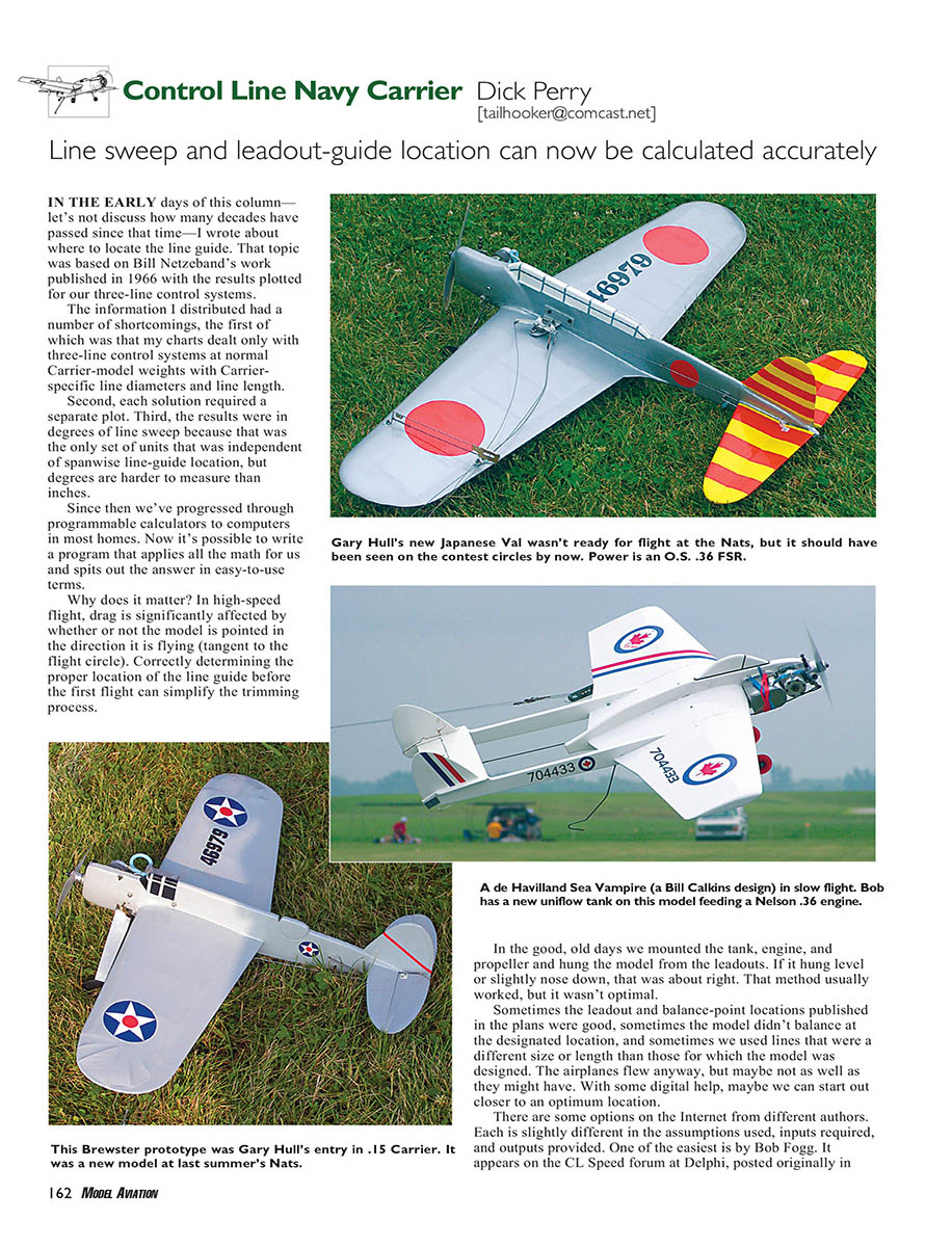
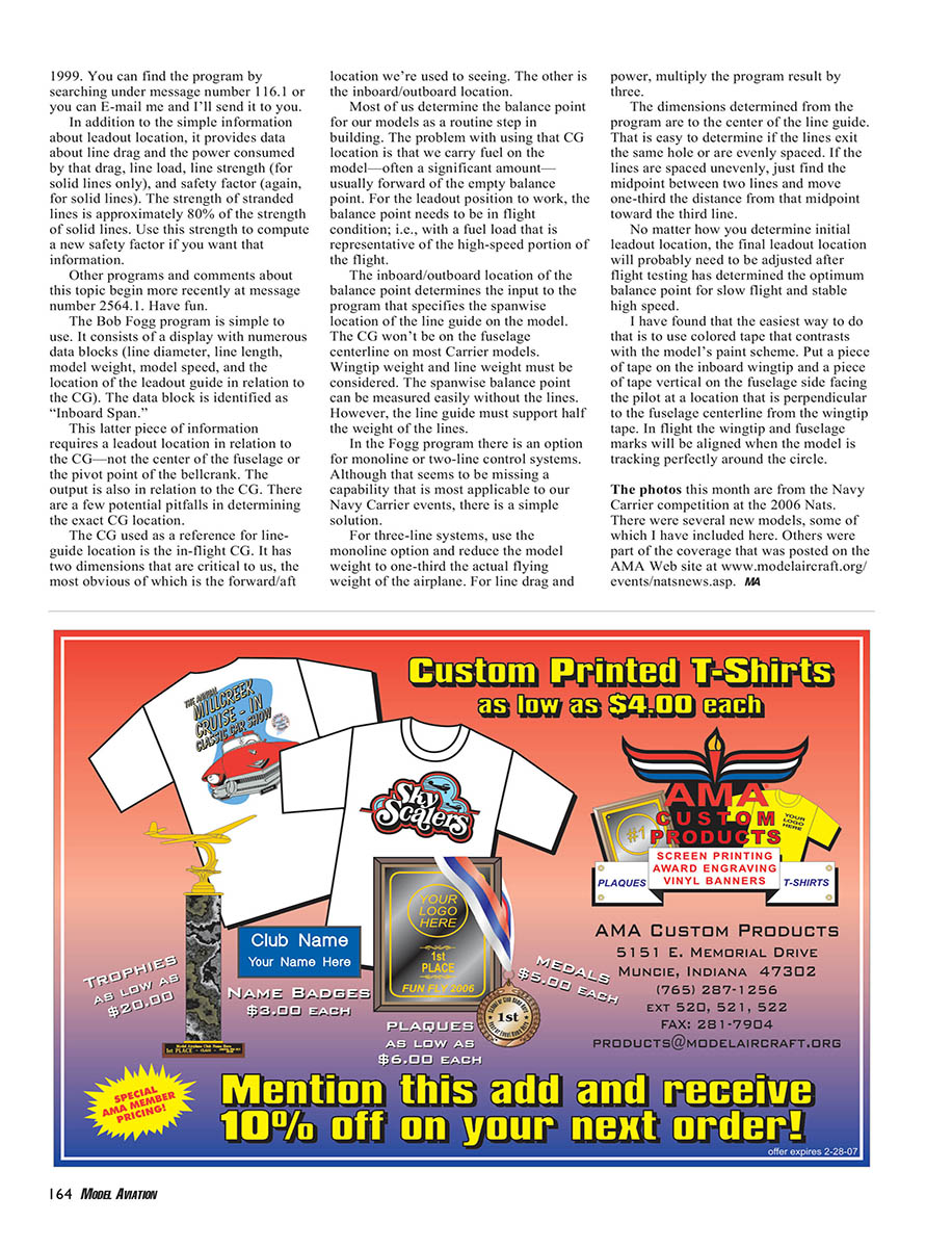
The photos this month are from the Navy Carrier competition at the 2006 Nats. There were several new models, some of which are included here. Others were part of the coverage posted on the AMA Web site: www.modelaircraft.org/events/natsnews.asp.
Transcribed from original scans by AI. Minor OCR errors may remain.

