
Control Line: Navy Carrier
Richard Perry
The Navy Carrier rules allow a bonus of five points for each engine over one used to power the model. One of the earlier attempts to take advantage of this bonus was a Grumman F7F Tigercat flown by Ray Randall. Ray was quite successful with this model, winning the 1960 Nats. He used two Johnson 35s, with the outboard engine running on a one-ounce tank so that it would stop after the high-speed run.
The rules have since changed to limit engine displacement and to require all engines to operate through the low-speed portion of the flight to receive full low-speed points. The recent introduction by K&B, SuperTigre, OS, and others of Schnuerle engines in smaller sizes provides very good performance potential for multi-engine Carrier flying.
The F7F Tigercat lends itself well to our event because the engines are widely spaced, allowing plenty of room for the props. The British Royal Navy had some carrier-based twins in the 1940s and 1950s, including carrier versions of the Hornet, Mosquito, and Meteor land-based fighters and the Short Sturgeon reconnaissance-bomber. Although these aircraft provide less propeller clearance, they have good potential.
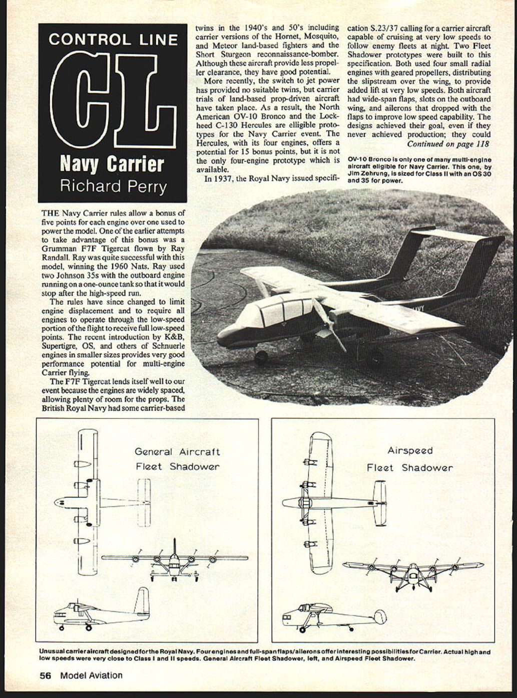
More recently, the switch to jet power eliminated most suitable twins, but carrier trials of land-based prop-driven aircraft have taken place. As a result, the North American OV-10 Bronco and the Lockheed C-130 Hercules are eligible prototypes for the Navy Carrier event. The Hercules, with its four engines, offers a potential for 15 bonus points, but it is not the only four-engine prototype available.
In 1937 the Royal Navy issued specification S.23/37 calling for a carrier aircraft capable of cruising at very low speeds to follow enemy fleets at night. Two Fleet Shadower prototypes were built to this specification. Both used four small radial engines with geared propellers, distributing the slipstream over the wing to provide added lift at very low speeds. Both aircraft had wide-span flaps, slots on the outboard wing, and ailerons that dropped with the flaps to improve low-speed capability. The designs achieved their goal; they could cruise at under 40 mph. The 3-view drawings show the configurations of these unusual aircraft.
Line rake angle and leadout location
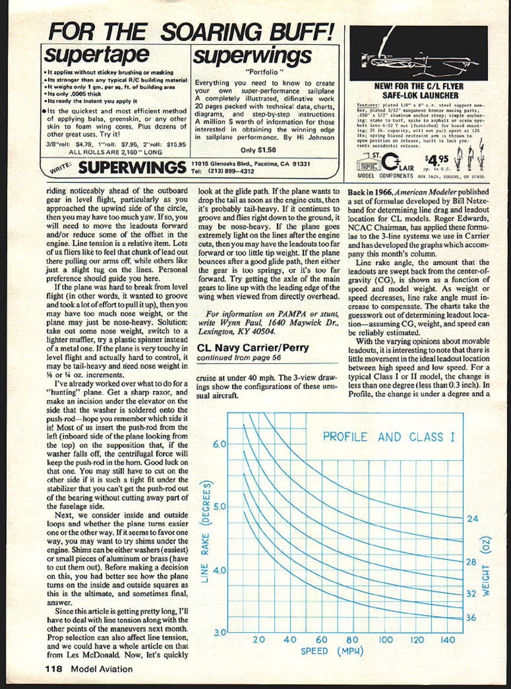
Back in 1966, American Modeler published a set of formulae developed by Bill Netzeband for determining line drag and leadout location for CL models. Roger Edwards, NCAC Chairman, has applied these formulae to the three-line systems we use in Carrier and has developed the graphs which accompany this column.
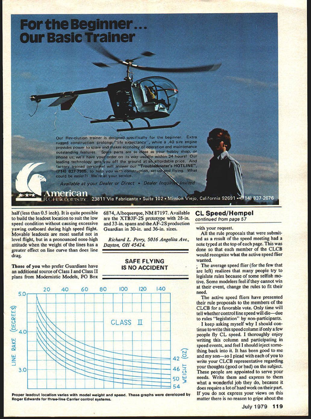
Line rake angle—the amount that the leadouts are swept back from the center of gravity (CG)—is shown as a function of speed and model weight. As weight or speed decreases, line rake angle must increase to compensate. The charts take the guesswork out of determining leadout location—assuming CG, weight, and speed can be reliably estimated.
With the varying opinions about movable leadouts, it is interesting to note that there is little movement in the ideal leadout location between high speed and low speed. For a typical Class I or II model the change is less than one degree (less than 0.3 inch). In profile models the change is under a degree and a half (less than 0.5 inch). It is quite possible to build the leadout location to suit the low-speed condition without causing excessive yawing outboard during high-speed flight. Movable leadouts are most useful not in level flight, but in a pronounced nose-high attitude when the weight of the lines has a greater effect on line curve than does line drag.
Those of you who prefer Guardians have an additional source of Class I and Class II plans from Modernistic Models, PO Box 6874, Albuquerque, NM 87197. Available are:
- XTB3F-2S prototype with 28 in. and 33 in. spans
- AF-2S production Guardian in 30 in. and 36 in. sizes
Richard L. Perry 5016 Angelita Ave. Dayton, OH 45424
SAFE FLYING IS NO ACCIDENT
Proper leadout location varies with model weight and speed. These graphs were developed by Roger Edwards for three-line Carrier control systems.
Transcribed from original scans by AI. Minor OCR errors may remain.

