
Control Line: Navy Carrier
Richard Perry
The subject for the next few months is engine speed control for the scale Carrier classes. I have discussed many different speed control systems in the past, from conventional suction systems with RC carburetors to pen-bladder pressure systems with large-bore modified carbs and idle mixture control. Suction systems offer competitive performance with the least amount of difficulty, but for many the few extra mph available with a pressurized fuel system are worth the extra effort involved.
In the past I have not described a fuel system unless I have used it myself, at least on the test stand. I am making an exception in the next few columns. I will discuss two pressure systems:
- On-off pressure
- Fuel meter
Although I have not used a fuel meter in Carrier myself, I am going to describe it since it is a very popular system used by many top competitors.
Both systems rely on an exhaust restrictor as the primary means of speed control. The use of exhaust restrictor throttles on model airplanes had its origin with Bob Smurthwaite (G-S Products) long before intake throttles were developed to any reasonable degree. Bob used an exhaust restrictor with a normal suction venturi, and that is the principle used with the on-off pressure system.
Exhaust restrictor: overview
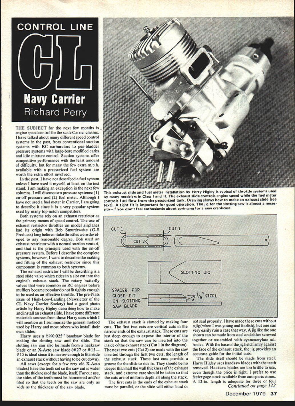
The exhaust restrictor described here is a steel slide valve which rides in a slot cut into the engine's exhaust stack. The rotary butterfly valves that were common on RC engines before mufflers became popular do not fit tightly enough to be used as an effective throttle.
Before describing the complete systems, I want to describe the making and fitting of the exhaust restrictor since this component is common to both systems.
Materials and saw options
- Harry Higley (in a pre-Nats issue of High-Low-Landing, the Newsletter of the CL Navy Carrier Society) used a 1/2 x 0.025-inch bandsaw blade for making the slotting saw and the slide.
- The slotting saw can also be made from a hacksaw blade or an X-Acto saw blade (#27 or #15 — #15 is ideal since it is narrow enough to fit inside an exhaust stack without having to be cut down).
- All saws (except a few very old X-Acto blades) have the teeth set so the saw cut is wider than the thickness of the blade itself. For our use, the sides of the teeth must be hammered and/or filed so that the teeth on the saw are only as wide as the thickness of the saw blade.
Cutting the exhaust stack slot
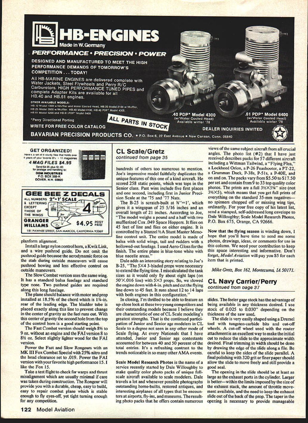
The exhaust stack is slotted by making four cuts:
- Make two vertical cuts in the narrow ends of the exhaust stack. These cuts are just deep enough to expose the interior of the stack so that the saw can be inserted into the inside of the exhaust stack.
- With the saw inserted through the first two cuts, make two longitudinal cuts along the length of the exhaust stack. These cuts provide the groove for the slide to ride in.
Notes:
- The longitudinal cuts should be no deeper than half the wall thickness of the exhaust stack. Extreme care must be taken so the cuts are of uniform depth all along the stack.
- The first cuts (the end cuts) must be parallel, or the slide will either bind or not seal properly.
Jig
The first cuts in the ends of the exhaust stack can be difficult to make accurately by hand. A jig can be made from steel and either screwed together or assembled with cyanoacrylate adhesive. With the base of the jig held firmly against the face of the exhaust stack, the jig provides an accurate guide for the initial cuts.
Slide material
- The slide itself should be made from steel.
- Harry Higley uses bandsaw blades with the teeth removed. Hacksaw blades are generally too brittle to use.
- I prefer to use feeler gauge stock available from auto parts stores. A 12-inch length is adequate for three or four exhaust slides.
- Feeler gauge stock has the advantage of being available in any thickness desired. I use stock of .025 to .030 inch depending on the thickness of the saw used.
Shaping and finishing the slide
- The slide is easily shaped using a Dremel tool with tungsten-carbide bits and cut-off wheels.
- A cut-off wheel used with the router attachment is an excellent way to make the initial cut to reduce the slide to the approximate width desired.
- Final trimming in width should be done by drawing the edge of the slide along a file. Be careful to keep the sides of the slide parallel.
- A final polishing with 320-grit or finer paper should allow the slide to move freely and still provide a good seal.
Slide opening and taper
- The opening in the slide should be at least as large as the exhaust ports in the cylinder. Larger is better within the limits imposed by the size of the exhaust stack, the amount of throttle movement available, and the need to keep the exhaust slide out of the back of the prop.
- The taper in the opening is necessary to provide manageable throttle response around idle.
Future columns will describe fuel meters and on-off pressure systems for use with the exhaust slide. For those who do not want to wait, a fuel meter like the one shown in Harry Higley's photo is available from:
Harry Higley 433 Arquilla Dr. Glenwood, IL 60425
Richard L. Perry 5016 Angelita Ave. Dayton, OH 45424
Transcribed from original scans by AI. Minor OCR errors may remain.

