
Control Line: Navy Carrier
Richard Perry
Of all the questions I get about carrier flying, the most common concerns the effects of acceleration on fuel. The original questions vary in detail, but when they involve engines that refuse to run consistently or that die on takeoff, the problem almost always can be traced to acceleration effects.
New source of Profile Carrier plans
Dave Trible, Air Mod Products, Box 411, Raymore, MO 64083, sent plans for profile models of a Douglas Devastator and a Japanese Val. Details:
- Douglas Devastator: 315 square inches, 44 in. span
- Japanese Val: 390 square inches, 43 in. span
- A Hellcat is also available
- Plans: $4.00 each
Dave's models are simple machines without flaps or other gadgets, and he reports good low-speed performance without instability. Both models have good scale outlines and have had success in Midwest carrier competition.
Airfoil and downthrust
Two unique features that contribute to low-speed handling are the airfoil and a 5° downthrust.
- The airfoil has a very blunt leading edge, producing usable lift to high angles of attack with gentle stall characteristics. Thickness varies from about 15% at the root to 23–25% at the tips.
- Five degrees of downthrust is uncommon on carrier models (or any CL model), and Dave claims it significantly improves low-speed handling. The downthrust and airfoil shape resulted from experiments with a model having a variable thrust line and removable wings.
Acceleration effects on fuel
A common problem among carrier models in all classes is that the engine goes rich or lean in the air, forcing a ground setting that is too lean or too rich to get a good in-air run. The probability of getting a correct setting the first time is low. With suction systems, a lean ground setting will often cause a loss of power on takeoff.
Uniflow tank venting, as used on stunt models, has a single vent tube ending near the fuel pickup tube. The tank supplies fuel under constant pressure at the pickup, but under flight conditions the pressure at the carburetor can vary considerably. This variation (and thus the fuel mixture) is caused by acceleration.
The lateral (inboard/outboard) position of the tank vent, relative to the carburetor and whether the vent is open to atmospheric or crankcase pressure, determines the effect of centrifugal acceleration on fuel supply:
- If the vent is inboard of the carburetor, centrifugal acceleration will increase fuel pressure at the carb as speed increases (richer mixture).
- If the vent is outboard of the carburetor, the engine will go leaner as speed increases.
The effects are reduced with pressure systems but still present. When the model accelerates on takeoff, fuel pressure at the carb can be reduced. The greater the distance from the end of the vent to the carburetor, the greater this effect. Moving the tank a foot below the engine would obviously kill a suction-fed engine — this is essentially the same effect on a smaller scale.
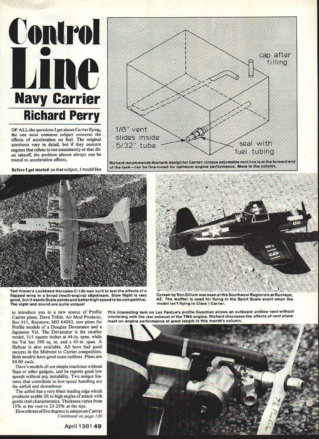
Movable vent tank
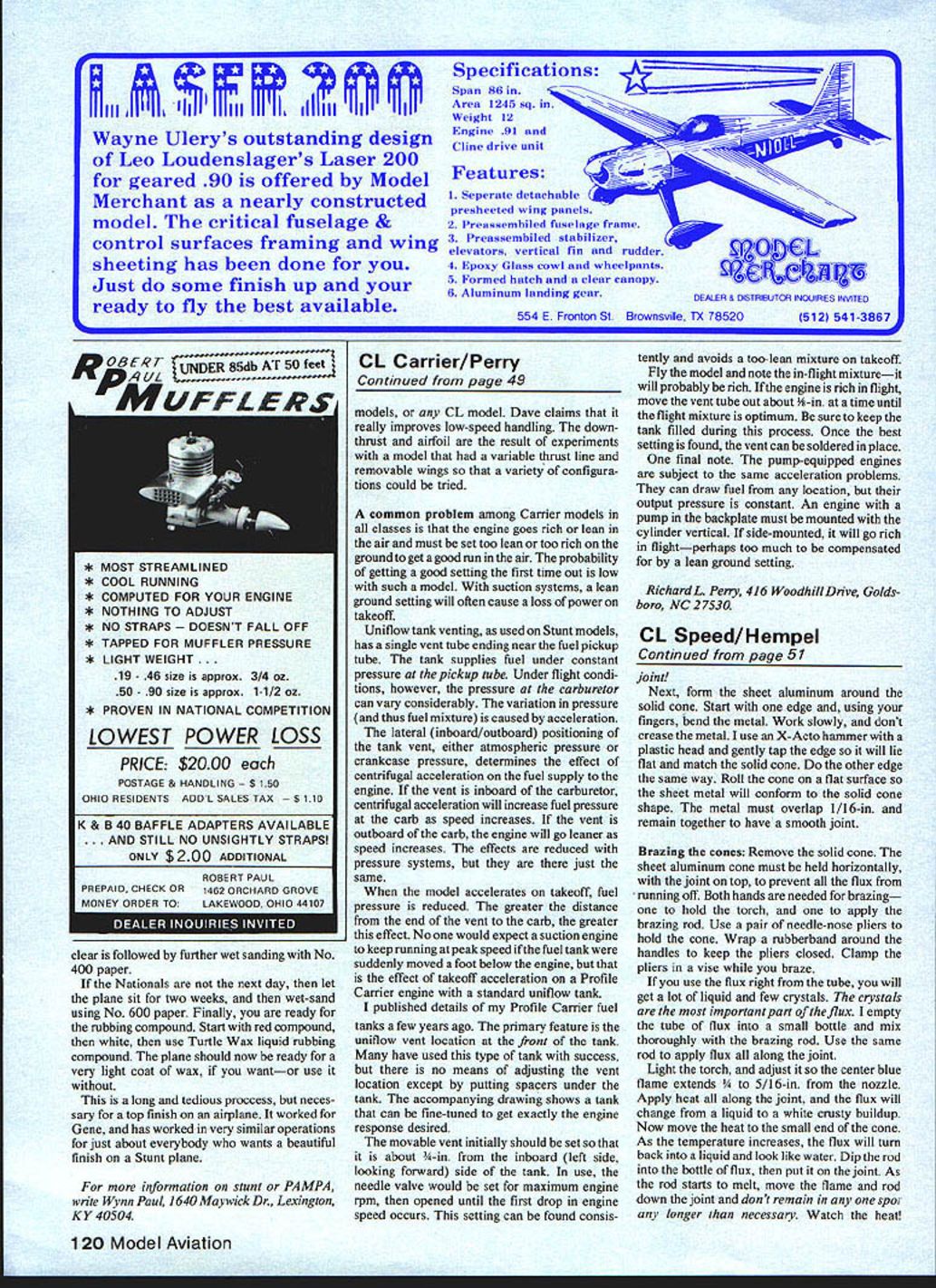
I published details of my profile carrier fuel tanks a few years ago. The primary feature is the uniflow vent located on the front of the tank. Many have used this type of tank successfully, but most offer no means of adjusting the vent location except by inserting spacers under the tank. The following tank design allows fine-tuning of vent position to achieve the desired engine response.
Initial setup and tuning procedure:
- Set the movable vent about 3/4 in. from the inboard (left, looking forward) side of the tank.
- Set the needle valve for maximum engine rpm on the ground, then open it until the first drop in engine speed occurs. This gives a consistent setting and helps avoid too-lean a mixture on takeoff.
- Fly the model and note the in-flight mixture — it will probably be rich. If rich in flight, move the vent tube outward about 1/8 in. at a time until the flight mixture is optimum.
- Keep the tank filled during this process. Once the best setting is found, solder the vent in place.
Pump-equipped engines
Pump-equipped engines are subject to the same acceleration-related problems. They can draw fuel from any location, but their output pressure is constant. An engine with a pump in the backplate must be mounted with the cylinder vertical. If side-mounted, it will go rich in flight — perhaps too much to be compensated for by a lean ground setting.
Richard L. Perry 416 Woodhill Drive Goldsboro, NC 27530
Transcribed from original scans by AI. Minor OCR errors may remain.

