
Control Line: Navy Carrier
Richard Perry
In my April column, I mentioned a potential problem with pump-equipped engines which are mounted horizontally rather than vertically. They tend to go rich in flight due to centrifugal acceleration, because the pump in the backplate is inboard of the carb, thus causing increased fuel pressure at the carb as the model's speed increases. The Perry pump carburetor has a means of compensating for this effect.
These carbs have a small weir in the fuel passage which is intended to restrict fuel flow when the engine is inverted, thus avoiding a rich setting. An adjusting screw is provided to control the amount of restriction. In use with a side-mounted engine on a CL model, this adjustment can be used to control the in-flight mixture — screw in to richen the mixture, screw out to lean the mixture. Once set, the mixture should need no major adjustments unless fuel or altitude change considerably. Some control of flight mixture will be possible using the normal needle valve.
GS Profile kits
I just received a letter from Bob Smurthwaite of GS Products which contained some good news for Carrier fliers. He is planning to reissue the Bearcat and Skyraider kits for Profile Carrier. These kits have been extremely popular in the past and have proven successful in competition — including a Nats win and two records. The GS kit parts are pre-shaped — even to having the stabilizer edges rounded and tapered and the hinge slots cut — so all that is required is a light sanding after assembly. The details of production schedule and price have not been finalized yet. Look for them.
Beginner's Corner
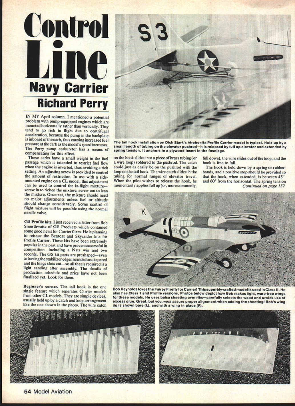
The tail hook is the one single feature which separates Carrier models from other CL models. They are simple devices, usually held up by a catch-and-loop arrangement like the one shown in the photo. The wire catch on the hook slides into a piece of brass tubing (or a wire loop) soldered to the pushrod. The catch could just as easily be on the pushrod with the loop on the tail hook. The wire catch slides in the tubing for normal ranges of elevator travel. When the pilot wishes to release the hook, he momentarily applies full up (or, more commonly, full down), the wire slides out of the loop, and the hook is free to fall.
The hook is held down by a spring or rubber bands, and a positive stop should be provided so that the hook, when extended, is between 45° and 60° from the horizontal. The spring tension should be light enough to allow the model to settle onto its tail skid if the model is placed on a smooth surface with the hook extended.
The end of the hook should form about a 45° angle with the main part of the hook. This way the hook can engage the arresting cables with the model in a normal three-point attitude as well as it can with the model flying just above the deck. The hook can be no more than one-third the length of the fuselage, and it should be made from 3/32-in. music wire, so that it will be strong enough to resist straightening out when engaging the arresting cable.
The tail hook can be attached to the model in a variety of ways. The photo shows a typical installation using 1/8-in. plywood reinforcements on the fuselage. A hardwood block can be inset into the fuselage and serve the same purpose. Hook placement should be such that the end of the hook is forward of the tail skid/wheel to avoid interference and missed arresting cables.
Scratch building
With very few kits available for our events, scratch building is almost a necessity. Original designs that appear at contests add interest to Carrier flying, both for contestants and spectators. The standard in Class I & II is sheeted or solid wing construction.
Strong, light wings can be carved from solid balsa, but getting balsa in the required thickness and density requires either a special order or an inordinate amount of luck. Foam cores have been used on models with straight-tapered wings. They have the advantage of allowing you to use the waste material from the core to provide support for the wing sheeting during the gluing process — the result being a perfectly warp-free wing.
Built-up, sheeted construction offers the best opportunity for obtaining a light structure, if care is used in wood selection and use of glue. Bob Reynolds uses the jig shown in the accompanying photos to build the warp-free and perfectly aligned wings for his Fairey Firefly models. The jig allows the complete wing, with dihedral, to be built as a unit. It is a method worth considering, especially if an individual, family, or club anticipates building more than one model of a particular design.
Richard L. Perry 416 Woodhill Dr. Goldsboro, NC 27530.
Transcribed from original scans by AI. Minor OCR errors may remain.

