
Control Line: Navy Carrier
Richard L. Perry
BACK IN THE October issue, I mentioned the utility and simplicity of suction fuel systems. This month I will discuss pressure systems and related speed control methods. The primary advantage that most modelers think of when they consider pressure fuel systems is that pressure means more power. This is true because a pressure fuel system allows the use of a larger air intake on the engine. The power increase possible with a pressure system is, however, small when compared to a large suction type of intake, and intake area is just a small part of total engine performance.
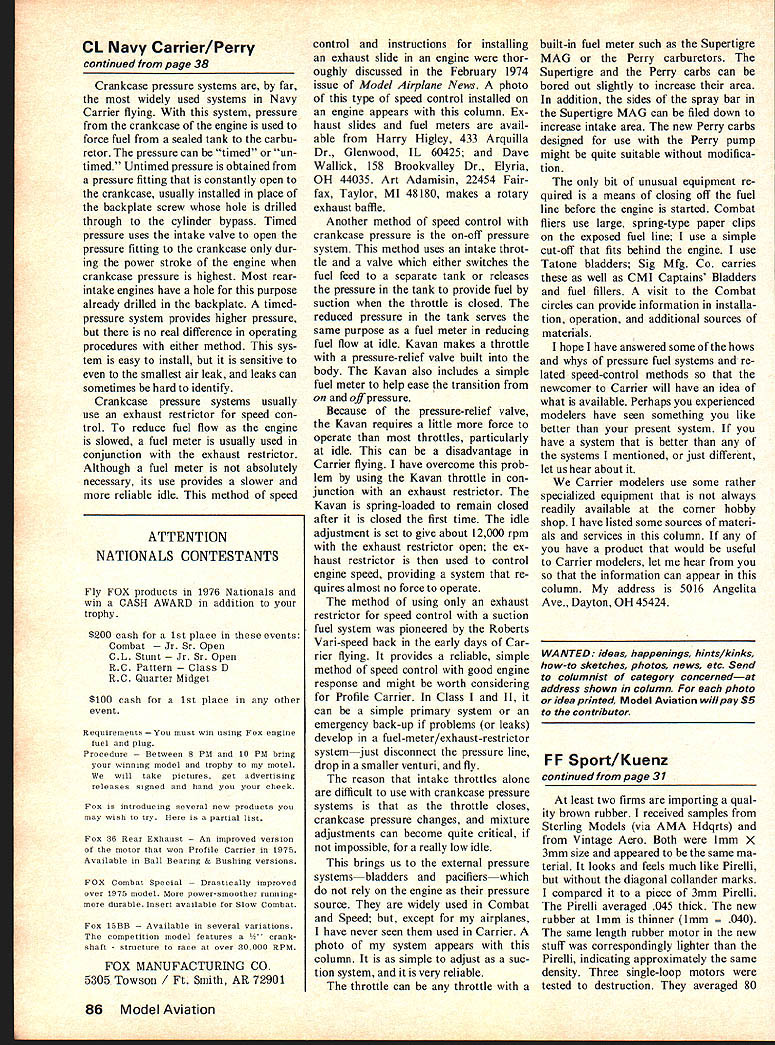
An additional advantage of pressure fuel systems for Carrier models is that they are insensitive to acceleration forces and aircraft attitude. Fuel tank placement is not critical, and this can be important in rather cramped fuselages of some scale Carrier ships.
I classify pressure systems by the pressure source, and I consider three main types: pump systems, crankcase pressure, and external pressure (bladder or pacifier).
Pump systems first attracted the attention of RC Pattern fliers about three years ago when Yamada Mfg. Co. developed a system (distributed by Model Rectifier Corp.) that used a pressurized tank to feed a regulator/pump that forced fuel to a large carburetor. Currently receiving much acceptance in this country is the Perry pump and carburetor system. The Perry pump is installed in place of the normal backplate on a front-intake engine and uses crankcase pressure variations to pump fuel to a large-bore carburetor designed for use with the pump. A pump system is expensive and currently limited to front-intake engines, but they are readily available and should be as simple to operate as a suction system.
Crankcase pressure systems are by far the most widely used. The system most widely used for Navy Carrier flying is the crankcase pressure engine used to force fuel from a sealed tank to the carburetor. Pressure can be timed or untimed. Untimed pressure is obtained by a pressure fitting constantly open to the crankcase. Usually installed in place of the backplate screw, a hole is drilled through the cylinder to bypass. Timed pressure uses the intake valve open to the pressure fitting into the crankcase during the power stroke when the engine crankcase pressure is highest. Most rear-intake engines have the hole for this purpose already drilled in the backplate. A timed pressure system provides higher pressure, but there is no real difference in operating procedures. Either method is easy to install but is sensitive to the smallest air leak. Leaks can sometimes be hard to identify.
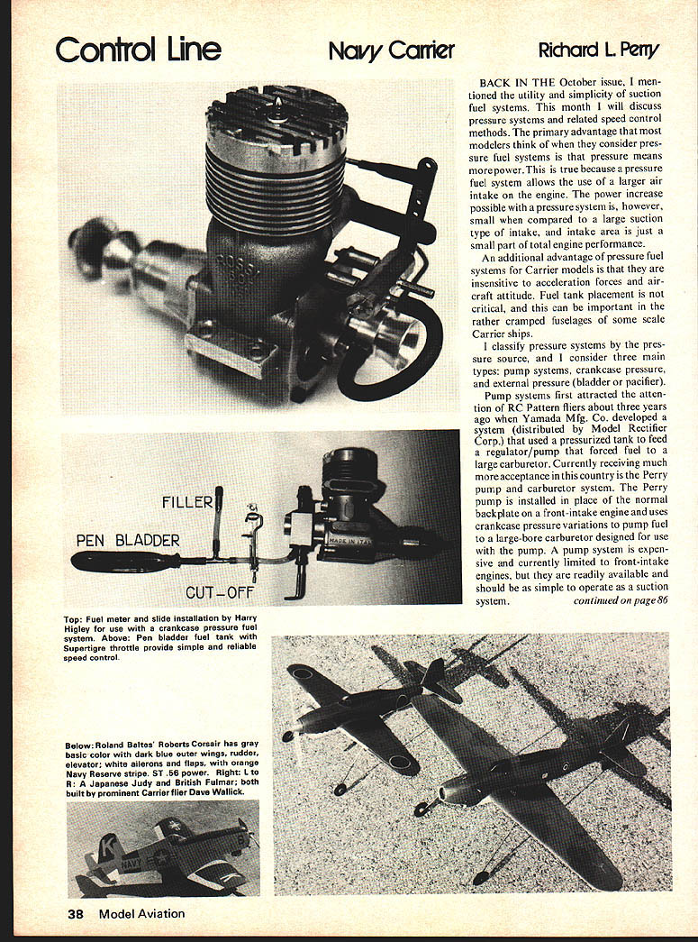
Crankcase pressure systems usually use an exhaust restrictor for speed control to reduce fuel flow when the engine is slowed. A fuel meter is usually used in conjunction with an exhaust restrictor. Although the fuel meter is not absolutely necessary, its use provides a slower, more reliable idle method of speed control. Control and instructions for installing an exhaust slide in an engine were thoroughly discussed in the February 1974 issue of Model Airplane News. A photo of this type of speed control installed on an engine appears with this column. Exhaust slides and fuel meters are available from Harry Higley, 433 Arquilla Dr., Glenwood, IL 60425; and Dave Wallick, 158 Brookvalley Dr., Elyria, OH 44035. Art Adamisin, 22454 Fairfax, Taylor, MI 48180, makes a rotary exhaust baffle.
Another method of speed control with the crankcase pressure is the on-off pressure system. This method uses an intake throttle and a valve which either switches the fuel feed to a separate tank or releases the pressure in the tank to provide fuel by suction when the throttle is closed. The reduced pressure in the tank serves the same purpose as a fuel meter in reducing fuel flow at idle. Kavan makes a throttle with a pressure-relief valve built into the body. The Kavan also includes a simple fuel meter to help ease the transition from on- and off-pressure.
Because of the pressure-relief valve, the Kavan requires a little more force to operate than most throttles, particularly at idle. This can be a disadvantage in Carrier flying. I have overcome this problem by using the Kavan throttle in conjunction with an exhaust restrictor. The Kavan is spring-loaded to remain closed after it is closed the first time. The idle adjustment is set to give about 12,000 rpm with the exhaust restrictor open; the exhaust restrictor is then used to control engine speed, providing a system that requires almost no force to operate.
The method of using only an exhaust restrictor for speed control with a suction fuel system was pioneered by the Roberts Vari-speed back in the early days of Carrier flying. It provides a reliable, simple method of speed control with good engine response and might be worth considering for Profile Carrier. In Class I and II, it can be a simple primary system or an emergency back-up if problems (or leaks) develop in a fuel-meter/exhaust-restrictor system — just disconnect the pressure line, drop in a smaller venturi, and fly.
The reason that intake throttles alone are difficult to use with crankcase pressure systems is that as the throttle closes, crankcase pressure changes, and mixture adjustments can become quite critical, if not impossible, for a really low idle.
This brings us to the external pressure systems — bladders and pacifiers — which do not rely on the engine as their pressure source. They are widely used in Combat and Speed; but, except for my airplanes, I have never seen them used in Carrier. A photo of my system appears with this column. It is as simple to adjust as a suction system, and it is very reliable.
The throttle can be any throttle with a built-in fuel meter such as the Supertigre MAG or the Perry carburetors. The Supertigre and the Perry carbs can be bored out slightly to increase their area. In addition, the sides of the spray bar in the Supertigre MAG can be filed down to increase intake area. The new Perry carbs designed for use with the Perry pump might be quite suitable without modification.
The only bit of unusual equipment required is a means of closing off the fuel line before the engine is started. Combat fliers use large, spring-type paper clips on the exposed fuel line; I use a simple toggle that fits behind the engine. I use Teflon bladders; Sig Mfg. Co. carries these as well as CMI Captains Bladders and fuel fillers. A visit to the Combat circles can provide information on installation, operation, and additional sources of materials.
I hope I have answered some of the hows and whys of pressure fuel systems and related speed-control methods so that the newcomer to Carrier will have an idea of what is available. Perhaps your engine models have shown something you like better than your present system. If you have a system that is better than any of the systems I mentioned, or just different, let us hear about it.
We Carrier modelers use some rather specialized equipment that is not always readily available at the corner hobby shop. I have listed some sources of materials and services in this column. If any of you have a product that would be useful to Carrier modelers, let me hear from you so that the information can appear in this column. My address is 5016 Angelita Ave., Dayton, OH 45424.
Transcribed from original scans by AI. Minor OCR errors may remain.

