
Control Line: Navy Carrier
Dick Perry
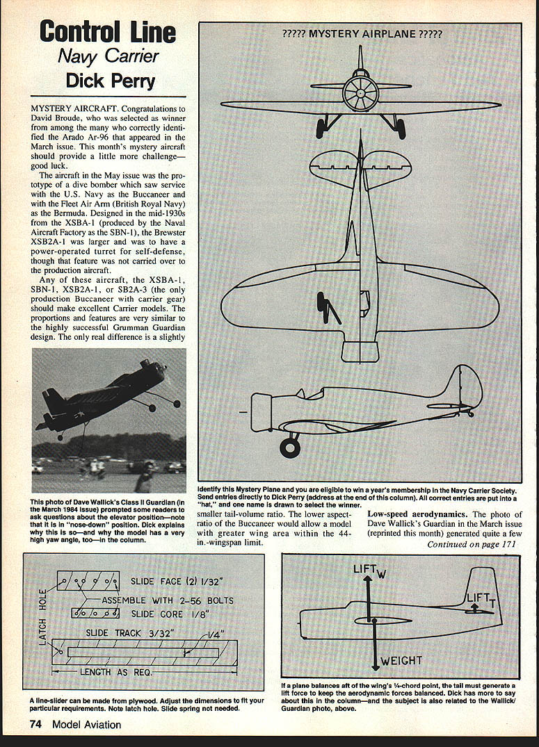
Mystery Aircraft
Congratulations to David Broude, who was selected as winner from among the many who correctly identified the Arado Ar-96 that appeared in the March issue. This month's mystery aircraft should provide a little more challenge—good luck.
The aircraft in the May issue was the prototype of a dive bomber which saw service with the U.S. Navy as the Buccaneer and with the Fleet Air Arm (British Royal Navy) as the Bermuda. Designed in the mid-1930s from the XSBA-1 (produced by the Naval Aircraft Factory as the SBN-1), the Brewster XSB2A-1 was larger and was to have a power-operated turret for self-defense, though that feature was not carried over to the production aircraft.
Any of these aircraft—the XSBA-1, SBN-1, XSB2A-1, or SB2A-3 (the only production Buccaneer with carrier gear)—should make excellent Carrier models. The proportions and features are very similar to the highly successful Grumman Guardian design. The only real difference is a slightly smaller tail-volume ratio. The lower aspect-ratio of the Buccaneer would allow a model with greater wing area within the 44-in. wingspan limit.
Identify this Mystery Plane and you are eligible to win a year's membership in the Navy Carrier Society. Send entries directly to Dick Perry (address at the end of this column). All correct entries are put into a "hat," and one name is drawn to select the winner.
Low-speed aerodynamics
The photo of Dave Wallick's Guardian in the March issue (reprinted this month) generated quite a few letters. Most questioned the inconsistency between the down elevator on Dave's model and my comment about flaps causing a nose-down pitching moment. I'll use this opportunity to identify the major cause of the down-elevator phenomenon and to discuss the related issue of line sliders. If you don't see the relationship between the two, read on; it should become more clear.
Call for submissions
As many who know me can attest, I can carry on at great length on areas where I have strong opinions. In the Stunt arena those would be airplane design, construction (not necessarily finish, as I've got a lot to learn from some real pros ... mostly in "Noo Yawk"), control systems, and the broad spectrum of Stunt philosophy and personalities.
Areas where I am frankly weak and would be cautious in making recommendations are engines, fuels, fuel systems, and the powerplant system in general. The most common picture at the Nats is one which shows me looking quizzically at my motor of the moment, wondering why it is less momentous now than earlier.
What I'm doing is begging for any and all materials you, the readers, can send me. Pictures are great, preferably black-and-white 5 x 7s; however, good, uncluttered color shots will reproduce, I'm told. Pictures earn $5 each when published. Technical info is good; however, if I feel strongly the material is not correct or might be misleading, I will either have to edit it or not use it at all. I will do my best to reply to all submissions, especially if one is requested and a SASE is included.
I would particularly appreciate being included on the mailing list of any and all newsletters which might remotely bear on the needs of Stunt fliers. Often, techniques and production items intended for one specialty have corollary applications in other fields.
Get those cards and letters coming to: Ted Fancher 158 Flying Cloud Isle Foster City, CA 94404
Fly Stunt!
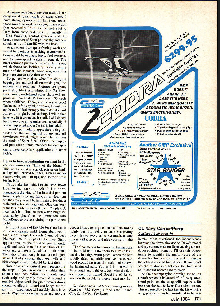
Hint of the Month — Laminating small curved outlines
A quick primer on laminating small curved outlines, such as rudder shapes, wing and tail tips, etc., from 1/32-in. balsa:
- Make the mold.
- I made mine from 3/4-in. bass, on which I rubber-cemented a drawing of the intended part cut from the plans for my Reno ship.
- Cut out the area you will be laminating, leaving a male and a female segment.
- Glue one segment to a suitable base (I used 1/8-in. ply).
- A nice touch is to line the area which might be touched by glue from the lamination with MonoKote, to prevent gluing the part to the mold.
- Prepare the strips.
- Cut strips of flexible 1/32 sheet balsa to the appropriate width (remember, you'll need eight strips for a 1/4-in. part thickness—1/4 in. is plenty for most Stunt applications).
- Soak them in a solution of hot water and ammonia for about a half hour. The ratio of ammonia is not critical—make it stinky enough that your wife and kids complain and it should be just right.
- Precurve and glue.
- For curves tighter than about a two-inch radius, gently stroke each strip around a rounded object until the grain breaks down enough to allow it to curl easily against the grain.
- Wipe away excess water and apply a good aliphatic resin glue (such as Tite-Bond) lightly but thoroughly to each succeeding piece. Try to avoid using too much, as any excess will seep out and glue your part to the mold.
- Clamp and cure.
- Clamp the laminations to the mold and allow them to cure at least one day in a dry, warm place.
- When fully dried, carefully remove the excess wood protruding from the mold and remove the laminated part.
- You will be amazed at the strength and lightness—just what the doctor ordered for Reno! Speaking of Reno, more on the problems there next month.
Down-elevator and line sliders
As the accompanying drawing (in the original column) shows, an aircraft which is balanced aft of the quarter-chord point will, in full-up trim, require a lift force on the tail to keep the tail up. This is caused by the fact that the lift which the wing produces can be considered to be acting at a point behind the center of gravity and so produces a nose-up moment. The tail must therefore produce a downward force to balance that moment.
When flaps are deflected they increase the lift of the wing and move the center of pressure forward, reducing the nose-up moment; therefore the tail must produce a greater downward force to maintain trim, resulting in down-elevator. The change in the wing's lift and in the downwash at the tail both contribute to this effect.
Line sliders, by limiting elevator travel and changing hinge-moment characteristics, can alter the trim condition and may exaggerate or hide the down-elevator effect. If sliders are used, they must be set so sufficient elevator authority remains for all intended flight conditions, and their influence on hinge moments and neutral position must be considered when trimming the model.
Propeller power effect
There is another effect which is even more pronounced. A propeller (or a jet intake), when an aircraft is operating at a high angle of attack, will change the direction of the incoming airflow in such a way as to cause a force perpendicular to the original direction of the airflow. This force is a vertical force if the aircraft is in level flight. (By this I mean that the model is neither climbing nor descending, even though the fuselage may not be in a "level" attitude.) When the propeller is mounted ahead of the balance point (as most of our models are configured), this force will tend to pitch the nose up. The force becomes stronger as angle of attack and/or power setting are increased.
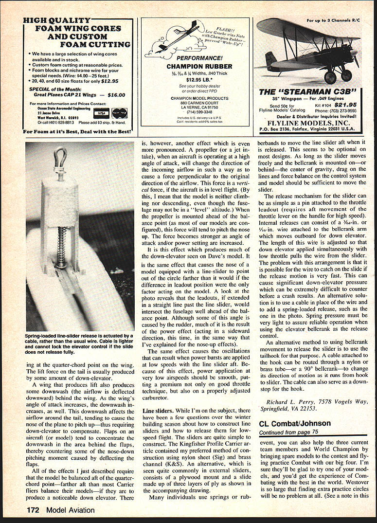
It is this effect which produces much of the down-elevator seen on Dave's model. It is the same effect that causes the nose of a model equipped with a line-slider to point out of the circle farther than it would if the difference in leadout position were the only factor acting on the model. A look at the photo reveals that the leadouts, if extended in a straight line past the line slider, would intersect the fuselage well ahead of the balance point. Although some of this angle is caused by the rudder, much of it is the result of the power effect (acting in a sideward direction, this time, in the same way that I've explained for the nose-up effect).
The same effect causes the oscillations that can result when power bursts are applied at low speeds with the line slider at the high setting. Because of this, power application at very low airspeeds should be smooth, putting a premium not only on good throttle technique but also on a properly adjusted carburetor.
Line sliders
While I'm on the subject, there have been a few questions over the winter building season about how to construct line sliders and how to release them for low-speed flight.
- Construction methods:
- My preferred method (shown in the Kingfisher Profile Carrier article) uses nylon sheet (Sig) and brass channel (K&S).
- An alternative common in external sliders is a plywood mount with a slide made up of three layers of ply.
- Movement:
- Many individuals use springs or rubber bands to move the line slider aft when it is released. This seems to be optional on most designs. As long as the slider moves freely and the bellcrank is mounted on—or behind—the center of gravity, drag on the lines and force balance on the control system and model should be sufficient to move the slider.
- Release mechanisms:
- A pin attached to the throttle leadout (requires aft movement of the throttle lever on the handle for high speed).
- Internal release using 1/8-in. or 3/32-in. wire attached to the bellcrank arm which moves outboard for down elevator. The wire length is adjusted so that the down elevator applied simultaneously with low throttle pulls the wire from the slider.
- Problem: the wire can catch on the slide if the release motion is very fast, causing significant down-elevator pressure and potentially a crash.
- Use a cable in place of the wire and add a spring-loaded release (spring pressure must be very light to assure reliable operation when using the elevator bellcrank as the release control).
- Use the tailhook as the release control. A cable attached to a hook can be routed through a nylon or brass tube—or a 90° bellcrank—to change its direction of motion from hook to slider. The cable can also serve as a down-stop for the hook.
Richard L. Perry 7578 Vogels Way Springfield, VA 22153
Transcribed from original scans by AI. Minor OCR errors may remain.

