
Control Line: Navy Carrier
Dick Perry
The Mystery Plane
The Mystery Plane in the July issue was the Boulton Paul Sea Balliol T. Mk. 21. The Balliol design began as the P.108, a three-seat, all-purpose advanced trainer with an Armstrong-Siddeley Mamba turboprop engine. The prototype made its first flight on March 24, 1948 and was the first aircraft in the world to fly with a turboprop power plant as the means of propulsion. The Royal Air Force production variant (Mk. 2) used a Rolls-Royce Merlin piston engine for power and deleted the extra seat. With a few equipment changes, a smaller propeller, and a tail hook the aircraft became the Mk. 21 for the Royal Navy, of which 30 were procured for the Fleet Air Arm.
The winner of the May contest is Eugene Nickels, Jr., whose name was selected from among over a dozen correct entries. Congratulations, Eugene.
There is no Mystery Plane contest this month because I am moving to Rapid City, SD and will not know my new address before this column goes to the printer. The feature will resume after I am moved in and get my drawing board set up once again.
Wing-tip protection
Current Carrier models use more weight in the outboard wing than was common in models of a few years ago. While the additional weight improves low-speed performance potential, it also can cause the outboard wing tip to contact the deck on a hard landing. It is not uncommon to see Carrier models with a worn spot on the bottom outboard trailing edge—especially when the models are flown over pavement for practice or in competition from a deck that is marked out on the ground.
A patch of Celastic (Sig Manufacturing Co.) at the outer end of the trailing edge can save wear and tear. Carl Goldberg Models manufactures a nylon wing skid which is light and very easy to install and which extends about 3/8 in. below the wing to keep the wing, itself, from dragging.
The heavier tip weight and the larger models being flown today combine to increase the potential for damage from another cause. Many Carrier decks use large eyebolts to support the arresting lines. When these eyebolts are placed at the edge of the deck (the only option on a standard wooden deck), it becomes possible under some circumstances for the wing leading edge near the tip to strike the eyebolt or to strike the center of the circular portion of the bolt. All that is needed is a heavy wing tip, a landing more than two feet right of the centerline of the deck, and a hard landing in the right spot relative to the eyebolt. I had never considered the potential hazard until I saw a couple of models lose part of their wings last year; one was my son's model. The easiest way to avoid the problem is to land in the center of the deck, but mistakes do happen.
It is also possible to reduce the potential for damage by adding small protective ramps in front of each eyebolt. These can be made from pieces of cheap 1 x 2 furring strip about five inches long. These pieces are cut across the diagonal to form triangles which can be placed in front of the eyebolts. They do not have to be attached to the deck if doing so would interfere with stacking the deck for storage. Ramps in front of the inboard eyebolts can help avoid another uncommon but potentially damaging occurrence: catching a control line on the eyebolt.
Tail hooks
Carrier models are different from models for other events in a number of ways, but the one difference mandated by the rule book is the tail hook. The paragraphs which follow run through some of the "tricks of the trade" relative to this part of a Carrier model.
The rules require that the tail hook be no longer than one-third the length of the fuselage. The rule specifies fuselage length, not model length; thus the usual interpretation is that the fuselage length includes model structure which may project beyond the fuselage structure. Normal material for the tail hook is 1/32-in. music wire. It is possible to use 1/64-in. diameter wire since the primary load on the wire is tension, but the smaller wire is not adequate in the actual hook portion. If smaller wire is used, the hook bend will have to be reinforced to prevent the hook from straightening under load and releasing the arresting line.
The tail hook pivot should be located aft on the fuselage. Forward mounting can cause a tendency for the model to rise onto its nose when the arresting line is engaged. I have mounted the hook as far forward as the wing trailing edge without serious problems. Another point to consider when locating the tail hook is that the end of the hook should not be adjacent to or immediately aft of the tail wheel or tail skid because such an arrangement could tend to keep the arresting lines out of the hook when rolling on the landing gear. The best location is to have the end of the hook forward of the tail skid/wheel. I have, however, used the tail skid as a down stop for the hook with the end of the hook about seven inches behind the skid and have not had any noticeable problems.
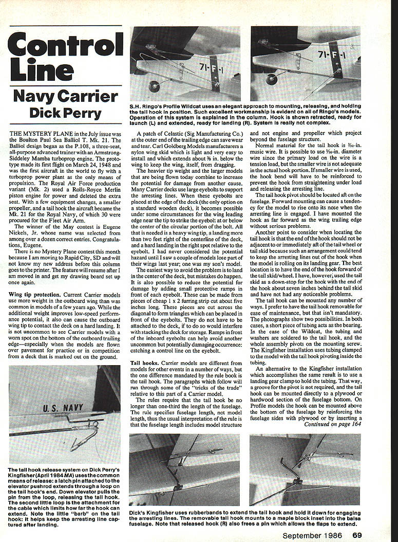
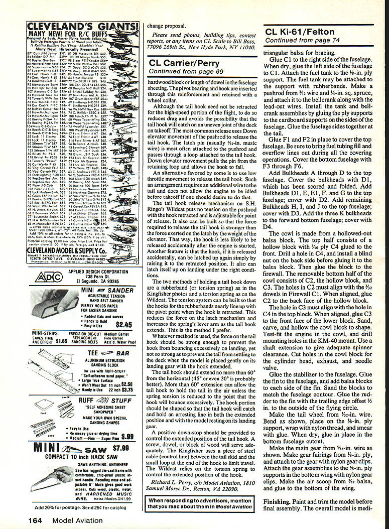
The tail hook can be mounted a number of ways. I prefer to have the tail hook removable for ease of maintenance, but that isn't mandatory. In both of the photographed examples a short piece of tubing acts as the bearing. In the case of the Wildcat, the tubing and washers are soldered to the tail hook and the whole assembly pivots on the mounting screw. The Kingfisher installation uses tubing clamped to the model with the tail hook pivoting inside the tubing.
An alternative to the Kingfisher installation that accomplishes the same result is to use a landing gear clamp to hold the tubing. That way, a groove for the pivot is not required, and the tail hook can be mounted directly to a plywood or hardwood section of the fuselage bottom. On profile models the hook can be mounted above the bottom of the fuselage by reinforcing the fuselage sides with plywood or by inserting a hardwood block or length of dowel in the fuselage sheeting. The pivot bearing and hook are inserted through this reinforcement and retained with a wheel collar.
Although the tail hook need not be retracted for the high-speed portion of the flight, doing so reduces drag and avoids the possibility that the tail hook will catch on an uneven joint of the deck on takeoff. The most common release uses down-elevator movement of the pushrod to release the tail hook. The latch pin (usually 1/2-in. music wire) is most often attached to the pushrod and passes through a loop attached to the tail hook. Down-elevator movement pulls the pin from the retaining loop and allows the hook to fall.
An alternative favored by some is to use low-throttle movement to release the tail hook. Such an arrangement requires an additional wire to the tail and does not allow the engine to be idled before takeoff if one should desire to do that.
The tail hook release mechanism on S. H. King's Wildcat puts no tension on the pushrod when the hook is retracted and is adjustable for the point of release. It also can be built so that the force required to release the tail hook is stronger than the force exerted on the latch by the weight of the elevator. That way, the hook is less likely to be released accidentally after the engine is started. Another feature is that the hook, if it is released accidentally, can be latched up again simply by raising it to the retracted position. It also can latch itself up on landing under the right conditions.
The two common methods of holding a tail hook down are:
- A rubber band (or tension spring), as in the Kingfisher photos.
- A torsion spring, as on the Wildcat.
The tension system can be built so that the hooks for the rubber bands nearly line up with the pivot point when the hook is retracted. This reduces the force on the latch mechanism and increases the spring's lever arm as the tail hook extends. This is the method I prefer.
Whatever method is used, the force on the tail hook should be strong enough to prevent the hook from bouncing excessively on landing, but not so strong as to prevent the tail from settling to the deck when the model is placed gently on its landing gear with the hook extended.
The tail hook should extend no more than 60° from the horizontal (45° or even 30° is probably better). More than 60° extension can allow the tail hook to hold the tail in the air unless the spring tension is reduced to the point that the hook will bounce excessively. The hook portion should be shaped so that the tail hook will catch and hold an arresting line in both the extended position and with the model resting on its landing gear.
A positive down-stop should be provided to control the extended position of the tail hook. A screw, dowel, or block of wood will serve adequately. The Kingfisher uses a piece of steel cable (control line) between the tail skid and a small loop at the end of the tail hook to limit travel. The Wildcat relies on the torsion spring to control the extended position of the hook.
Richard L. Perry c/o Model Aviation 1810 Samuel Morse Dr. Reston, VA 22090
Transcribed from original scans by AI. Minor OCR errors may remain.

