
Control Line: Navy Carrier
Dick Perry
Mystery Plane contest
The winner of the Mystery Plane contest in the July issue is Monty Greenly (Long Beach, CA). His was one of only four entries to correctly identify the Boulton Paul Sea Balliol trainer used by the Royal Navy. Joe Wagner provided an interesting bit of additional information from his research: although the Balliol was a Boulton Paul design, the Sea Balliol was produced by Blackburn, a more traditional supplier of aircraft for the Royal Navy.
Carrier engines
Profile: Carrier engines have seen many types over the years, but recent history favors down-sized versions of larger Schnuerle-ported engines — most notably the Tune-Hill conversion of the OS .40 FSR and the K&B 5.8. These engines are heavy and expensive. Recently, two lighter-weight alternatives intended for Combat competition have appeared:
- Cipolla .36
- Available from Doc Passen, 608 West Main, P.O. Box 111, Jasonville, IN 47438 (tel. 812/665-3723).
- Real lightweight at 7 ounces (without throttle).
- ABC Schnuerle with front intake and rear exhaust.
- More details: Charlie Johnson’s “CL Combat” column in the September 1986 Model Aviation.
- Fox .36 Combat Special Mk-VI
- Available direct only from Fox, 5305 Towson Avenue, Fort Smith, AR 72901 (tel. 501/646-1656).
- Price: $80.
- Return to the twin-ball-bearing configuration of the Mk-IV, but with a new crankshaft, new piston/cylinder metallurgy, and a larger-diameter wrist pin.
- The Mk-V carb should fit the traditional square Fox intake.
I have not run either engine. Charlie Johnson expects the Cipolla to be comparable to the Mk-IV Foxes. Advertising claims for the Fox Mk-VI say it will outrun a Mk-IV by 10 mph. Judge for yourself or talk to a Combat flier who owns one of these engines. I would be happy to hear from anyone with experience with either engine.
Removable wing
How do you put three Carrier models in a compact car to go to a contest? How do you ship a model to the Nats in a UPS-sized container? With the trend toward larger Carrier models, the answer is often, “You can’t!” — unless you can take the models apart.
I built my first removable-wing Carrier models in 1985 because I couldn’t see a good way to get six 44-in. span models into my car and still have room for suitcases and flying gear. My MO-1s use two 1/4-in.-dia. nylon bolts and a 6-32 machine screw to attach the wing. The bellcrank is fuselage-mounted so the wing mounting is not subject to the line-pull loading. The fuselage under the wing is open to allow access to the control system.
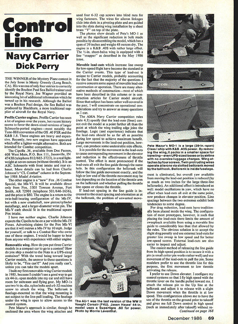
Pete Mazur’s approach is similar, though he enclosed the area where the wing attaches and used four 6-32 cap screws into blind nuts for wing fasteners. The wires for aileron linkages slide into slots in a pivoting plate and are guided into the slots during wing installation by a sheet-brass “V” on top of the plate.
Photos show details of Pete’s MO-1 as well as the significant reduction in bulk made possible by disassembling the model. His model has a 39-inch span and weighs 48 ounces dry. The engine is a K&B .40S with rather large offset. The 1/2-in. sheet-balsa wing is equipped with a line “snapper” as described in the May 1986 issue.
Movable lead-outs
Movable lead-outs, which increase line sweep for low-speed flight, have become the standard in Carrier events. This type of lead-out is unique to Carrier models, and many reader questions concern construction or operation details. Since construction methods have been covered extensively elsewhere, I’ll concentrate on operational considerations and answers to common questions.
#### Rules and general principle The AMA Navy Carrier competition rules (rule 4.3) specify that the lead-outs (lines) cannot exit the model at a point farther aft than the point where the wing trailing edge joins the fuselage. Logic and experience indicate that the lead-outs should be as far aft as possible during low speed to achieve maximum benefit. Large movements in lead-out position, however, can produce undesirable side effects.
#### Effects on controls Movement in the lead-outs can cause corresponding movement in the elevator and reduction in the effectiveness of throttle control. The effect is most pronounced if the lead-outs all exit the model through the same hole in the line guide. In this configuration the bellcrank will follow the line guide movement exactly, and the high-to-low end of throttle movement may be lost depending on the throttle-arm location on the bellcrank and whether pulling the throttle line opens or closes the throttle.
If lead-out spacing in the line guide is increased to match the spacing and orientation at the bellcrank, the unwanted movement is eliminated, but overall yaw available by moving the lead-out position is reduced (by as much as two inches with large three-line bellcranks).
An additional effect introduced when model oscillations in yaw have no effect is that, with the lead-outs exiting the same point, they can produce changes in elevator position. Increasing spacing eliminates the unwanted movement, but reduces the overall yaw available by moving the lead-out position.
#### Drag and external lead-outs For drag reduction, lead-outs have traditionally been placed inside the wing. The configuration of most prototypes, however, is such that placing the lead-outs there limits the amount of sweepback available when using a movable line guide to considerably less than the rules allow. The obvious solution is to accept the slight drag penalty and use external lead-outs for greater line sweep in low speed and for better low-speed steadiness. External lead-outs are also easier to inspect and adjust.
#### Release mechanisms The easiest method of releasing the line guide from its high-speed position is to secure it with a pin (a small cotter pin works well) and use movement of the lead-outs to pull the pin out. Some modelers prefer to use the throttle line for this purpose, so the first movement to low throttle activates the release.
I prefer to use Down elevator. I configure my control systems so that if I fly high speed with the throttle lever on the handle pulled toward me, I attach the release pin to the Up line at the bellcrank and adjust it to release with a slight Down movement when the throttle is at low speed. This configuration allows me to use the throttle on the ground prior to takeoff and gives me full Down control in high speed without releasing the line slider. One could also use a flexible line or pushrod-and-bellcrank arrangement connected to the tail hook so that the lines would be released as the tail hook falls.
It is essential that once the line guide is released it must immediately move fully aft and stay there. Common methods to achieve this:
- Use a rubber band to pull the line guide aft immediately after release.
- Use the drag of the lines to pull it aft (bellcrank position must be well aft of the center of gravity for this method to work reliably).
A bellcrank mounted at the balance point combined with a free-sliding line guide and a spring to move it aft will often result in a line guide that moves back and forth in flight, producing potentially serious control problems.
#### Oscillations and adjustments Some models oscillate badly in low speed. Smooth application of power can help prevent oscillations from starting, but getting the proper combination of lead-out position and outboard wingtip weight for the particular model can significantly reduce the tendency.
In general:
- Most models improve if line sweep increases.
- Most models improve if tip weight is increased (this is often the first thing people try).
- Some models respond oppositely, so adjustable tip weight and lead-out stops are appropriate.
- Increasing line sweep usually requires less tip weight for satisfactory low-speed flight.
New address
I've settled in at my new home, although I spend most of my time deployed with my unit to Malmstrom Air Force Base, MT. By the time you read this, I should be home with my modeling gear unpacked and able to answer my mail.
Richard L. Perry 10035 Deadwood Ave., Ellsworth AFB, SD 57706
Transcribed from original scans by AI. Minor OCR errors may remain.

