
Control Line: Navy Carrier
By Dick Perry
Except for a casual mention from time to time, it has been 10 years since I've taken time in this column to discuss wing flaps in any great detail. Since the readers have, no doubt, changed over the years and because the style of flying is rather different now than it was a decade ago, this seems a good time to bring up the subject again.
Background
The original Carrier rules very much favored high speed over low speed in the scoring equations. The models that predominated under those rules tended to be small. Class I models of 125–140 sq. in. wing area, Class II models of 200–230 sq. in., and Profile models very close to the 300 sq. in. minimum were common. Low speeds were flown in a near-level attitude with the wing providing the lift (as opposed to the present nose-high prop-hanging that has become popular in recent years).
Wing flaps then, as now, added weight and complexity. Although their use contributed to improvements in low speed, they did not provide a significant scoring advantage, especially when offset by a slight degradation in high speed; however, most Class I and Class II models used flaps (as long as the prototype was equipped with them). The primary reasons for using them were that they improved low-speed handling, and, because of the drag they added, allowed engines to idle at a higher (and more reliable) speed. The slower speeds possible with flaps also made landings easier.
Profile models, with their lighter weights, larger wings, and RC engines which idled more slowly and reliably, did not need flaps for the same reasons that Class I and II models needed them. Their use on Profile models was largely a matter of personal preference, though achieving the last margin of performance generally dictated use.
Carlos Aloise's Condor and Harry Higley's Carrier Pigeon were flapped designs which were capable of 15 mph low speeds in level flight and which carried their masters to the winner's circle many times.
The change in scoring which gave more emphasis to low speed tended to favor flapped airplanes. The larger models which are prevalent in the designs being produced today, however, show a trend away from flaps. Prop-hanging low-speed flight does not benefit from flaps to the same degree that level-attitude low-speed flying did, and many builders are opting for reduced weight, drag, and complexity.
Flap Benefits and Trade-offs
As in the past, however, the edge in overall performance seems to favor a flapped model. The slightly better low-speed performance demonstrated by flapped models in prop-hanging flight is probably the result of additional lift and drag produced by the portion of the wing that is in the prop blast.
In building a model with flaps, a modeler has two basic options:
- Connect the flaps to the tail hook with pushrods and horns so that the flaps are lowered as the hook falls.
- Actuate the flaps by spring tension using a latch mechanism of some kind to hold the flaps up for high-speed flight.
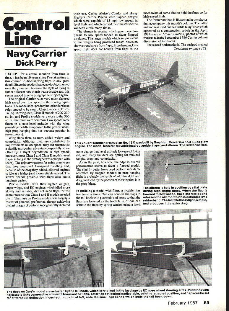
The former method is illustrated in the photos that accompany this month's column. The latter method was used on the Profile Kingfisher which appeared as a construction article in the April 1984 issue of Model Aviation; photos of that installation were used in the September 1986 Carrier column discussion of tail hooks.
I have used both methods. The pushrod method offers more potential for adjusting flap deflection to suit individual flying style and contest conditions. It also weighs more and produces more drag on exposed installations such as are common on Profile models. The disadvantages are slight, however, and are probably outweighed by the advantages when considering total performance and adaptability to different flying conditions.
How Flaps Affect Flight
Flaps function by changing the camber of the wing of which they are a part. They cause the wing to produce a higher lift coefficient for a given angle of attack. They also produce a negative pitching moment which causes the nose to pitch down. As flaps are deflected, drag increases, and the airflow around the tail is affected. All these factors combine in different ways for each airplane. The general tendency is toward "ballooning" or "floating" on most Carrier models, particularly Profiles.
The model may require some down elevator as speeds increase above the stall. Higher speeds may also require attitudes which are more nose-down than the normal level-flight attitude. Because of these facts, ballooning tends to be caused more by the pilot's reluctance to apply more down elevator than "normal" to lower the nose below the "normal" attitude. The effect is enhanced by the fact that wind produces much larger relative changes in airspeed as the model moves around the circle in low-speed flight. Compensating for these changes requires much greater change in angle of attack than at higher speeds.
The effects described above will vary with flap deflection; the greatest effect occurring in the first 30% of flap deflection on most models. Adjustable flap deflection can be useful in trimming a model to varying wind conditions. Less flap deflection will generally improve handling in windy conditions.
Differential Flaps and Ailerons
Some modelers like to use differential flap deflection to produce a rolling tendency away from the center of the circle. Increases in deflection beyond about 30% produce more drag while the other effects are increased relatively little by comparison. The effect is most pronounced, therefore, at the lesser flap settings. At greater flap deflections the outward-rolling effect may be balanced by an increase in drag on the inboard wing which will try to move the nose toward the center of the circle.
The key to adequate rolling effect is to use differential flap settings only at lesser flap deflections or to use a separate aileron on the outboard wing which has a very large upward deflection to better balance the drag on the inboard and outboard wings.
Aileron movement can be accomplished by springs (or rubber bands) or by connecting horns on flap and aileron to a reversing bellcrank in the wing. The method I prefer produces less drag and uses less material than the horn-and-bellcrank method. The release mechanism which holds the aileron in place for high-speed flight consists of a piece of heat-shrink tubing soldered to a piece of tubing. As the flap moves down, the tubing rotates, thereby releasing the aileron.
Author Contact
Richard L. Perry 10035 Deadwood Ave. Ellsworth AFB, SD 57706
Transcribed from original scans by AI. Minor OCR errors may remain.

