
Control Line: Navy Carrier
Dick Perry
1988 NATS
1988 NATS. If you read the minutes of the August Executive Council meeting (in the November 1986 AMA News), you noticed that the site for the 1988 Nats is still under investigation. Cam Martin reports that one of the sites being considered is Fentress Naval Aviation Field south of Norfolk, Virginia. This is, no doubt, good news for the modelers in the southeastern United States. Vince Mankowski and Howard Crispin have surveyed the site and are looking at potential layouts for the flying activities. One of the plans calls for Carrier to be flown over grass.
Although some Carrier contests are flown over grass, most of these use grass because pavement is not available. The preparation required to provide a grass flying circle which will allow safe landings (no cartwheels) takes many months, and that won't happen at Fentress.
If Fentress is a typical military airfield it is rather rough, and the grass is cut by a tractor about once a month. If these conditions sound as bad to you as they do to me, please join in writing to AMA and requesting that Nats planners make an effort to schedule Carrier flying on pavement to reduce the potential for damaging models which land off the deck.
Three-line control systems
Continuing the series on some of the basics of Carrier modeling, this month I'll discuss setting up the three-line control systems commonly used on Carrier models.
The three-line control systems used by the vast majority of Carrier modelers started out as J. Roberts systems manufactured by Sturdi-Built. J. Robert Smurthwaite, who designed the original bellcranks and handles, updated and improved them a few years ago and marketed the new design under the G-S Products logo. These control units and handles are now manufactured by LR Products (7787 Archdale Ave., Detroit, MI 48228) and can be ordered direct if local hobby shops cannot supply them.
Rigging controls to provide proper neutral elevator and adequate control throw for the engine is not difficult. Add the six-inch line-length tolerance, and it can be a little challenging, especially for someone who has not had any experience with three-line systems.
Practices common in other CL events don't work well. The variations in most ready-made lines are such that even if lead-outs are the proper length to use one set of ready-made lines, changing to another set could exceed the line-length tolerances. Putting three equal-length lead-outs on the bellcrank won't allow the use of three equal-length control lines because of the line spacing at the handle.
The easiest solution is to use lines that you finish yourself, but even this procedure is not without potential problems. The procedure that I use was developed over many years and has worked well for me. Start by tying the throttle lever on the handle so that it cannot move out of the full-aft position.
Measure and finish the two elevation lines for proper elevator neutral position relative to the handle. An adjustable clevis on the pushrod or line clips of different size can correct minor deviations in neutral position after the elevation lines are finished.
Finish one end of the throttle line, and connect it to the handle. Have a friend hold the handle and apply enough tension so that the lines sag six inches to a foot and do not touch the ground. Pull lightly on the throttle lead-out to ensure that it is properly extended, but do not pull hard enough to move the throttle arm. Next put enough tension on the throttle line so that it sags exactly as far as the elevation lines; mark the throttle line finish. If the model has movable lead-outs, lock them in the forward position during line construction.
This procedure should produce lines that are the proper length, allow full throttle movement, and provide a proper neutral elevator position relative to the handle. Because each line is specially fit, they should be marked to allow them to be properly reconnected if they are removed from the handle.
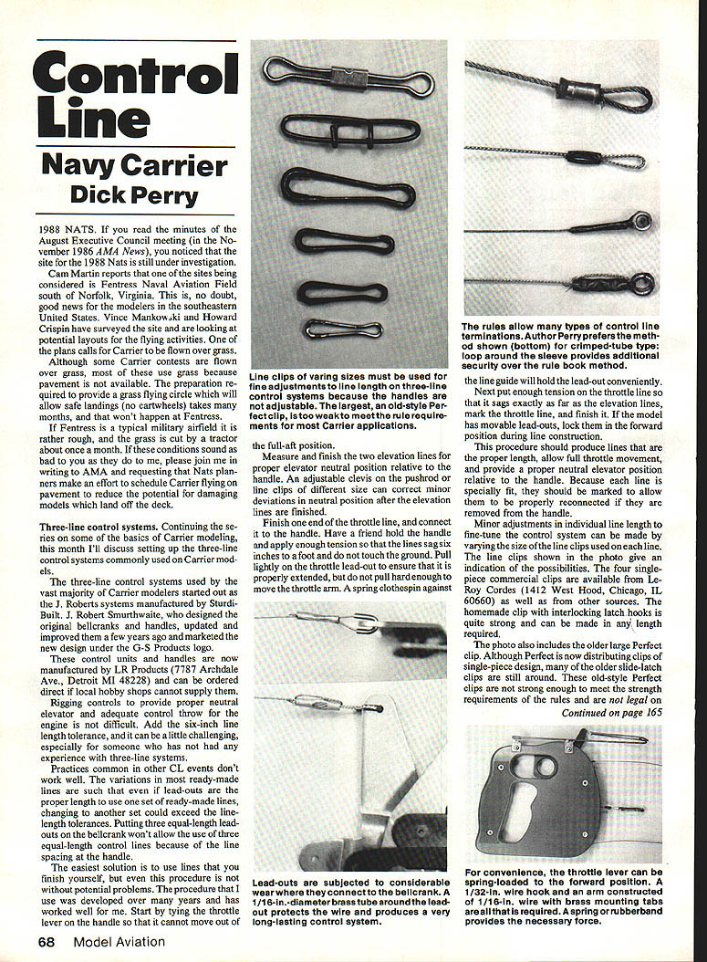
Minor adjustments in individual line length to fine-tune the control system can be made by varying the size of the line clips used on each line. The line clips shown in the photo are one-piece commercial clips available from LeRoy Cordes (1412 West Hood, Chicago, IL 60660) as well as from other sources. The homemade clip with interlocking latch hooks is quite strong and can be made in any length required.
The photo also includes the older large Perfect clip. Although Perfect is now distributing clips of single-piece design, many of the older slide-latch clips are still around. These old-style Perfect clips are not strong enough to meet the strength requirements of the rules and are not legal on most Carrier applications.
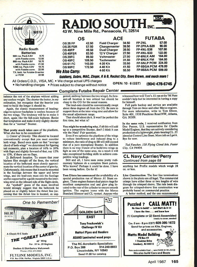
Some manufacturers, such as Sig for their lines, loop the line around the outside of the sleeve before running it through the sleeve a third time. This method provides an additional mechanical lock similar to that achieved with a wrapped line termination.
The best method is the wrapped construction shown in the photo and described in the AMA rule book. The fine copper wire in lamp cord produces a small-diameter line termination which is neat and strong and which avoids the possibility of damaging the line in the crimping process, a potential problem on smaller lines. A light coating of epoxy glue will ensure that the line wrapping remains secure.
I do not solder multi-strand lines or lead-outs, and I discourage others from soldering them. Although soldering can be done safely, there are potential pitfalls. Excessive heat can weaken the line. Solder can flow down the cable and stiffen a short length of it, causing flexing stress to be concentrated at the point where the solder ends. Corrosive flux can travel along the interior of the cable and is difficult to neutralize. The resulting internal corrosion can be difficult to detect.
The use of eyelets or thimbles to reduce line wear is recommended by the rules but is not very practical at the bellcrank end of the lead-out. The increased wear at the bellcrank can be compensated for by using significantly larger cable for the lead-outs, but I prefer to use hard brass tubing sleeves as shown in the photos. A 1/16-in.-diameter brass tube is placed around the lead-out and bent in a U-shape with round-nose pliers or a drill bit. The line with the sleeve in place is routed through the bellcrank hole which has been enlarged to 3/32 or 7/64 in. to allow free movement. The line is then finished using one of the AMA-approved methods from the rule book.
Please note that the crimped termination in the photo is not constructed according to the rule book. I did it hurriedly, for the photo only, and didn't recognize my error until too late to take new photos. The sleeve is crimped in only one place rather than two, and the pliers were not round-nosed. (I lost mine in my last move.)
Handle modification
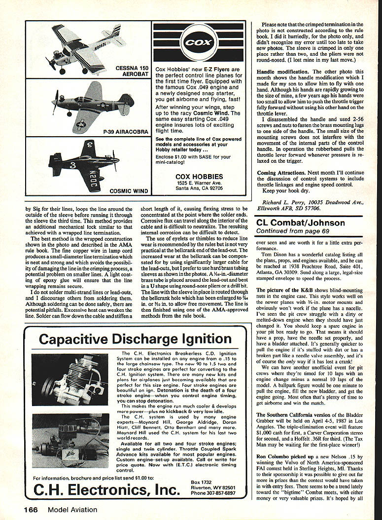
The other photo this month shows the handle modification which I made for my son to allow him to fly with one hand. Although his hands are rapidly growing to the size of mine, a few years ago his hands were too small to allow him to push the throttle trigger fully forward without using his other hand on the throttle lever.
I disassembled the handle and used 2-56 screws and nuts to fasten the brass mounting lugs to one side of the handle. The small size of the mounting screws does not interfere with the movement of the internal parts of the control handle. In operation the rubber band pulls the throttle lever forward whenever pressure is relaxed on the trigger.
Coming Attractions
Next month I'll continue the discussion of control systems to include throttle linkages and engine speed control. Keep your hook dry.
Richard L. Perry 10035 Deadwood Ave., Ellsworth AFB, SD 57706.
Transcribed from original scans by AI. Minor OCR errors may remain.

