
Control Line: Navy Carrier
Dick Perry
Proper credit
The exhaust duct (for rear-exhaust engines, made from an elbow plumbing fixture) which I described in the August issue was primarily the work of Stan Johnson. He and Orin Humphries, the one who sent me the drawings, have been using them quite extensively with good results. My apologies to Stan for not including his name in the original description.
Profile kits
I mentioned two profile kits in the last column which are remakes of the old Sterling P-51 Mustang and Yak-9. I have since had a chance to examine one of the P-51 kits and found it to be of good quality. The parts are sawn, not die-cut. The balsa is straight and light, and the plywood is five-ply aircraft grade, not the three-ply lightweight type found in some kits. Parts fit was generally good with some minor adjustments required to improve the mating of a few parts.
A model constructed from either of these kits should be light and very competitive. The only modifications required would be for the three-line control system and the tail hook. The P-51 landing gear is bent from 3/32-in. wire. For carrier use, 1/8-in. wire should be substituted.
The kits are manufactured by A.J.'s Free Flight Service, 4840 East Leisure, Fresno, CA 93727; phone (209) 255-2422.
GS kits availability
A recent letter from Cam Martin (1540 Bridle Creek Blvd., Virginia Beach, VA 23464) indicates that the GS kits may be made available again in small lots. According to a letter received by Cam, Bob Smurthwaite is willing to issue a limited number of these kits from parts he has in storage. Cam has offered to serve as a point of contact to collect the names of those interested in the GS kits. He has a market-survey form which he will send you if you provide him with an addressed, stamped envelope. He will consolidate the information and send it on to Bob Smurthwaite.
The cost will be in the $40–$45 range, but these kits are very highly finished. Those who have built one will tell you that the model can be built, literally, without sandpaper. Hinge slots are cut; fuselage, wing tips, and tail surfaces are rounded and tapered; all parts are sawn; and the fit of the parts is excellent. The models are designed as profile carrier models, so no modifications of any kind are required. Those who prefer moveable lead-outs will have to add them, since the kits are designed with fixed leadouts.
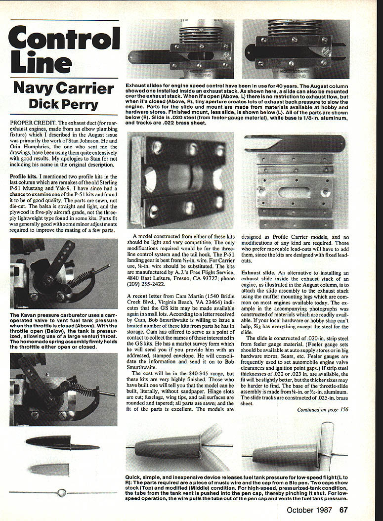
Exhaust slide
An alternative to installing an exhaust slide inside the exhaust stack of an engine, as illustrated in the August column, is to attach the slide assembly to the exhaust stack using the muffler mounting lugs which are common on most engines available today. The example in the accompanying photographs was constructed of materials which are readily available at your local hardware or hobby shop.
Materials and parts:
- Slide: .020-in. strip steel from feeler-gauge material (if available, .022 or .023 in. is slightly better).
- Base: 1/8-in. or 3/32-in. aluminum.
- Slide tracks: .025-in. brass sheet.
- Fasteners: example uses 4-40 flat-head screws for mounting and 2-56 screws for attaching slide tracks (smaller screws will work).
Tools:
- No special tools required beyond those found in most modelers' workshops.
- A Dremel tool or similar greatly speeds the work; carbide bits and cutoff wheels work well.
- A drill press is helpful, but a hand drill will suffice.
Construction and fitting:
- The method of construction is obvious from the photographs. The dimensions depend on the dimensions of the exhaust stack to which the assembly will be attached; size and shape are not critical.
- The opening in the slide should be tapered. If the slide is used with an intake throttle (used primarily for fuel metering as described in the August column), the length of the taper may need adjusting for optimum performance.
- If the fuel mixture is correct at idle and full throttle but the engine gets excessively rich as the throttle is advanced slowly from idle, the taper should be shorter (so it opens faster).
- If the engine is slightly lean just above idle, the taper should be longer so the exhaust opening increases more slowly as the slide is moved.
- Adjustments can also be made to the amount of throttle arm movement in relation to the exhaust slide movement; some experimentation is usually required.
- The best method to maintain a straight, smooth edge on the brass slide tracks is to use the finished edge of the strip as the interior side of the track. Cut the base wider than the finished dimension and use 1/4-in.-wide brass strip for the track parts. After the assembly is complete and tested, cut the outside edges to final size in one operation to produce a smooth edge with minimum work.
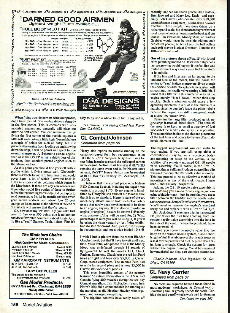
On-off pressure (switched pressure/suction system)
The advent of throttles that contain their own fuel metering has greatly simplified engine speed control. The use of exhaust restrictors in conjunction with a metering carburetor can allow for quite reliable engine speed control with pressure fuel systems (as described in the August column). An alternative system exists which, although a little harder to construct, offers extreme ease of adjustment: a switched pressure/suction system. This system operates on pressure for high speed, then switches to suction for low speed. On low speed the intake throttle is fixed, and engine speed is controlled solely by an exhaust restrictor.
The Kavan pressure carburetor provides the easiest method of installing a switched pressure/suction system. It contains a valve which releases the pressure in the fuel tank when the throttle is closed. They were expensive and never in great supply. The photo shows a Kavan carb with an over-center spring used to hold the carb in both open and closed positions. The carb is opened manually before the engine is started and closed by a small-diameter cable as the throttle is closed for the first time. The very flexible cable allows for free movement of the exhaust restrictor without movement of the intake throttle.
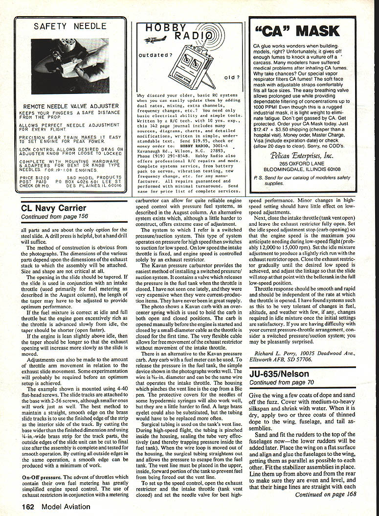
Alternative pinch-valve device:
- Any carb with a fuel metering unit can be modified to release the pressure in the fuel tank.
- A simple device that works well is to pinch the vent line at the cap using the cap from a Bic pen. Protective covers for the lower ends of some hypodermic syringes will also work, though they are a little harder to find. A large brass eyelet could be used, but the tubing would need more frequent replacement.
- Surgical tubing is used on the tank's vent line. During high-speed flight, the tubing is pinched inside the housing, sealing the tube effectively (trapping pressure inside the fuel tank). When the wire loop is moved out of the housing, the surgical tubing straightens and allows the pressure to escape from the fuel tank.
- The vent line must be placed in the upper, inside, forward portion of the tank to prevent fuel from being forced out the vent line.
Setting up the speed control:
- Open the exhaust restrictor so the intake throttle (tank vent closed) is open, and set the needle valve for best high-speed performance. Minor changes in the high-speed setting should have little effect on low-speed adjustments.
- Close the intake throttle (tank vent open) and leave the exhaust restrictor fully open. Set the idle-speed adjustment stop (carb opening) so that the engine speed is the maximum you anticipate needing during low-speed flight (probably 12,000 to 15,000 rpm).
- Set the idle mixture adjustment to produce a slightly rich run with the exhaust restrictor open.
- Close the exhaust restrictor gradually until the desired low speed is achieved, and adjust the linkage so that the slide will stop at that point when the bellcrank is in the full low-speed position.
Notes:
- Throttle response should be smooth and rapid and independent of the rate at which the throttle is opened.
- Systems like this tend to be tolerant of changes in fuel, altitude, and weather when they are fairly rich in idle mixture once initial settings are satisfactory.
If you are having difficulty with your current pressure-throttle arrangement, consider a switched pressure/suction system; you may be pleasantly surprised.
Richard L. Perry 10035 Deadwood Ave., Ellsworth AFB, SD 57706
Transcribed from original scans by AI. Minor OCR errors may remain.

