
Control Line: Navy Carrier
By Dick Perry
1988 NATS
1988 NATS! It's official — the 1988 Nats will be held in the vicinity of Norfolk, VA. Preliminary plans call for a gathering of all forms of modelers for competition, convention, etc. It should be quite a show if it all materializes as planned.
Those of you who read about the Norfolk possibilities in the April issue and brushed them aside as being too far in the future or too uncertain to take action should think again and get out your pens. To refresh your memories, the CL site will be Fentress Naval Aviation Field. Preliminary plans are for the Carrier competition to be flown over grass, and the grass at Fentress will not be good. We need to start now to get the Carrier flying over pavement. The person to write to is Nats Manager Vince Mankowski at AMA HQ. Send your letters through me and I will forward them.
1987 NATS
The 1987 Nats are history as this is being written, and you have all had the opportunity to read about them in Pete Mazur's article in the November 1987 issue of Model Aviation. Of particular note were the low-speed times of 41 minutes turned in by Bill Melton and LeRoy Cordes. I hope to provide a summary of the equipment used by all of the CL Navy Carrier contestants at this year's Nats in a future column. For now, I'll just add my congratulations to the winners and especially to Bill Melton, who won the Eugene Ely Award for the second time. Well done, Bill.
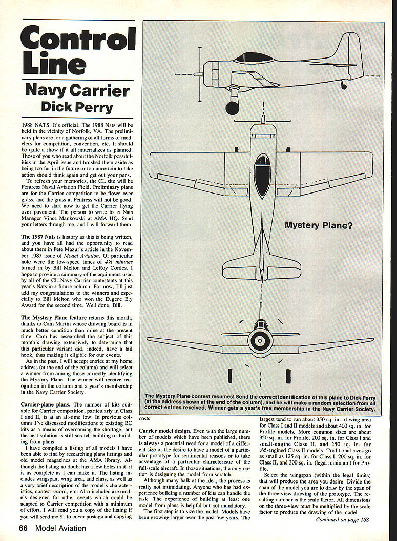
Mystery Plane
The Mystery Plane feature returns this month, thanks to Cam Martin, whose drawing board is in much better condition than mine at the present time. Cam has researched the subject of this month's drawing extensively to determine that this particular variant did, indeed, have a tail hook, thus making it eligible for our events.
As in the past, I will accept entries at my home address (see Contact below) and will select a winner from among those correctly identifying the Mystery Plane. The winner will receive recognition in the column and a year's membership in the Navy Carrier Society.
Carrier-plane plans
The number of kits suitable for Carrier competition, particularly in Class I and II, is at an all-time low. In previous columns I've discussed modifications to existing RC kits as a means of overcoming the shortage, but the best solution is still scratch-building or building from plans.
I have compiled a listing of all models I have been able to find by researching plans listings and old model magazines at the AMA library. Although the listing no doubt has a few holes in it, it is as complete as I can make it. The listing includes wingspan, wing area, and class, as well as a very brief description of the model's characteristics, contest record, etc. Also included are models designed for other events that could be adapted to Carrier competition with a minimum of effort.
I will send you a copy of the listing if you will send me $1 to cover postage and copying costs.
Carrier model design
Even with the large number of models that have been published, there is always a potential need for a model of a different size, the desire to have a model of a particular prototype for sentimental reasons, or to take advantage of a particular characteristic of the full-scale aircraft. In those situations, the only solution is designing the model from scratch.
Although many balk at the idea, the process is really not that intimidating. Anyone who has had experience building a number of kits can handle the task. The experience of building at least one model from plans is helpful but not mandatory. The first step is to size the model.
Models have been growing larger over the past few years. Typical sizes and ranges are:
- Profile: common about 350 sq. in.; legal minimum 300 sq. in.
- Class I: common about 200 sq. in.; traditional sizes down to 125 sq. in.
- Class II: small-engine Class II about 200 sq. in.; .15-engined Class II about 250 sq. in.
- Larger models: around 350 sq. in. for Class I and II; Profile sometimes about 400 sq. in.
Select a wingspan within legal limits that will produce the area you desire. Divide the span of the model you are to draw by the span of the three-view drawing of the prototype. The resulting number is the scale factor. All dimensions on the three-view must be multiplied by the scale factor to produce the drawing of the model.
Drawing and scaling methods
Once the scale factor is determined, the outlines of the major components of the model can be duplicated in a variety of ways.
- Traditional mechanical enlargement: Use mechanical drawing procedures to enlarge the three-views. This is probably the most accurate method, although the other methods described are accurate enough when done carefully.
- Reference-line (perpendicular intercept) method: Draw a reference line through each component (along the length of the fuselage, across the span of the wing, etc.), then draw perpendicular lines across the reference line at convenient intervals (wing/fuselage junctions, changes in contour, likely former or rib locations, etc.). Reproduce each perpendicular on the paper for the model using the scale factor as multiplier. At each cross line, measure the distance from the reference line to the outer contour on the three-view, multiply by the scale factor, and transfer it to the drawing.
- Grid method: Draw a grid over the three-view and a larger grid on the paper to be used for the model (larger by the scale factor). Plot the outlines by matching the grid points where the three-view outlines cross the grid lines and connect the points.
- Photographic/projection method: Photograph the three-view (35 mm slides are convenient), project the image at the appropriate size onto paper (tape it to the wall) and trace the outlines. Care must be used to ensure the camera is on a line perpendicular to the center of the three-view and the projector is perpendicular to the paper to minimize distortion. Three-views can also be copied onto acetate using a standard office copier and projected using an overhead (TV-graph) projector.
The details of the basic structure can be copied from a kit, plans, or a model of similar size and class and should present no particular problem as long as the builder sticks to materials and construction methods with which he is familiar. Be sure to allow for the thickness of fuselage and wing sheeting when drawing formers and ribs.
Using these procedures, a working drawing can be produced, which is the first step in turning your dream into reality. Good luck.
Contact
Richard L. Perry 10035 Deadwood Ave. Ellsworth AFB, SD 57706
Transcribed from original scans by AI. Minor OCR errors may remain.

