
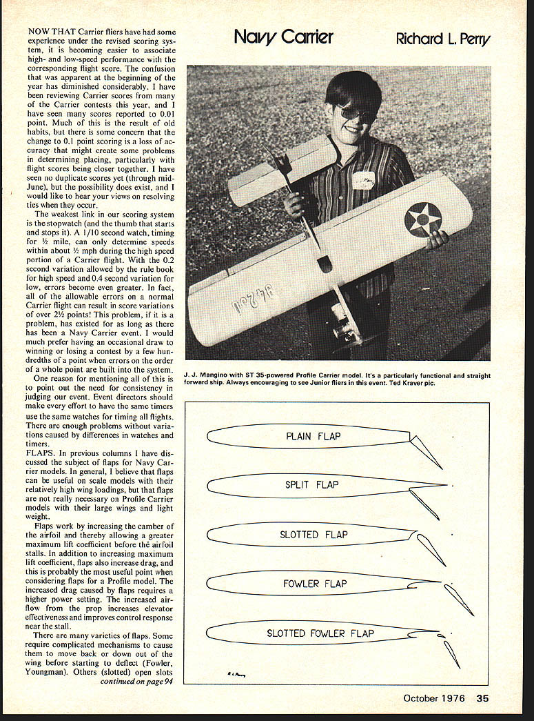
Navy Carrier
Richard L. Perry
NOW THAT Carrier fliers have had some experience under the revised scoring system, it is becoming easier to associate high- and low-speed performance with the corresponding flight score. The confusion that was apparent at the beginning of the year has diminished considerably. I have been reviewing Carrier scores from many of the Carrier contests this year, and I have seen many scores reported to .01 point. Much of this is the result of old habits, but there is some concern that the change to .1 point scoring is a loss of accuracy that might create some problems in determining placing, particularly with flight scores being closer together. I have seen no duplicate scores yet (through mid-June), but the possibility does exist, and I would like to hear your views on resolving ties when they occur.
The weakest link in our scoring system is the stopwatch (and the thumb that starts and stops it). A 1/10 second watch, timing for 1/2 mile, can only determine speeds within about 1/2 mph during the high speed portion of a Carrier flight. With the 0.2 second variation allowed by the rule book for high speed and 0.4 second variation for low, errors become even greater. In fact, all of the allowable errors on a normal Carrier flight can result in score variations of over 2 1/2 points! This problem, if it is a problem, has existed for as long as there has been a Navy Carrier event. I would much prefer having an occasional draw to winning or losing a contest by a few hundredths of a point when errors on the order of a whole point are built into the system.
One reason for mentioning all of this is to point out the need for consistency in judging our event. Event directors should make every effort to have the same timers use the same watches for timing all flights. There are enough problems without variations caused by differences in watches and timers.
FLAPS
In previous columns I have discussed the subject of flaps for Navy Carrier models. In general, I believe that flaps can be useful on scale models with their relatively high wing loadings, but that flaps are not really necessary on Profile Carrier models with their large wings and light weight.
Flaps work by increasing the camber of the airfoil and thereby allowing a greater maximum lift coefficient before the airfoil stalls. In addition to increasing maximum lift coefficient, flaps also increase drag, and this is probably the most useful point when considering flaps for a Profile model. The increased drag caused by flaps requires a higher power setting. The increased airflow from the prop increases elevator effectiveness and improves control response near the stall.
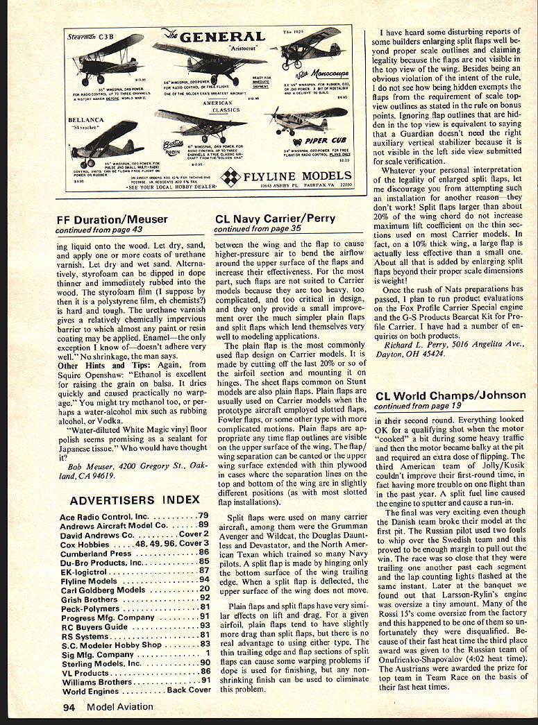
There are many varieties of flaps. Some require complicated mechanisms to cause them to move back or down out of the wing before starting to deflect (Fowler, Youngman). Others (slotted) open slots Between the wing and the flap to cause higher-pressure air to bend the airflow around the upper surface of the flaps and increase their effectiveness. For the most part, such flaps are not suited to Carrier models because they are too heavy, too complicated, and too critical in design, and they only provide a small improvement over the much simpler plain flaps and split flaps which lend themselves very well to modeling applications.
The plain flap is the most commonly used flap design on Carrier models. It is made by cutting off the last 20% or so of the airfoil section and mounting it on living hinges. The sheet flaps common on Stunt models are also plain flaps. Plain flaps are usually used on Carrier models when the prototype aircraft employed slotted flaps, Fowler flaps, or some other type with more complicated motions. Plain flaps are appropriate any time flap outlines are visible on the upper surface of the wing. The flap/wing separation can be canted or the upper wing surface extended with thin plywood skins across where the separation lines on the top and bottom of the wing are in slightly different positions (as with most slotted flap installations).
Split flaps were used on many carrier aircraft; among them were the Grumman Avenger and Wildcat, the Douglas Dauntless and Devastator, and the North American Texan which trained so many Navy pilots. A split flap is made by hinging only the bottom surface of the wing trailing edge. When a split flap is deflected, the upper surface of the wing does not move.
Plain flaps and split flaps have very similar effects on lift and drag. For a given airfoil, plain flaps tend to have slightly more lift than split flaps. The trailing edge and flap sections of split flaps can cause some warping problems if dope is used for finishing; any non-shrinking finish can be used to eliminate this problem.
I have heard some disturbing reports of some builders enlarging split flaps well beyond proper scale outlines and claiming legality because the flaps are not visible in the top view of the wing. Besides being an obvious violation of the intent of the rule, I do not see how being hidden exempts the flaps from the requirement of scale top-view outlines as stated in the rule on bonus points. Ignoring flap outlines that are hidden in the top view is equivalent to saying that a Guardian doesn't need the right auxiliary vertical stabilizer because it is not visible in the left side view submitted for scale verification.
Whatever your personal interpretation of the legality of enlarged split flaps, let me discourage you from attempting such an installation for another reason — they don't work! Split flaps larger than about 20% of the wing chord do not increase maximum lift coefficient on the thin sections common to most Carrier models. In fact, on a 100% thick wing, a large flap is actually less effective than a small one. About all that is added by enlarging split flaps beyond their proper scale dimensions is weight!
Once the rush of Nats preparations was passed, I plan to run product evaluations on the Fox Profile Carrier Special engine and the G-S Products Bearcat Kit for Profile Carrier. I have had a number of enquiries on both products.
Richard L. Perry, 5016 Angelita Ave., Dayton, OH 45424.
Transcribed from original scans by AI. Minor OCR errors may remain.

