
Control Line: Navy Carrier
Dick Perry 9009 Arley Dr. Springfield, VA 22153
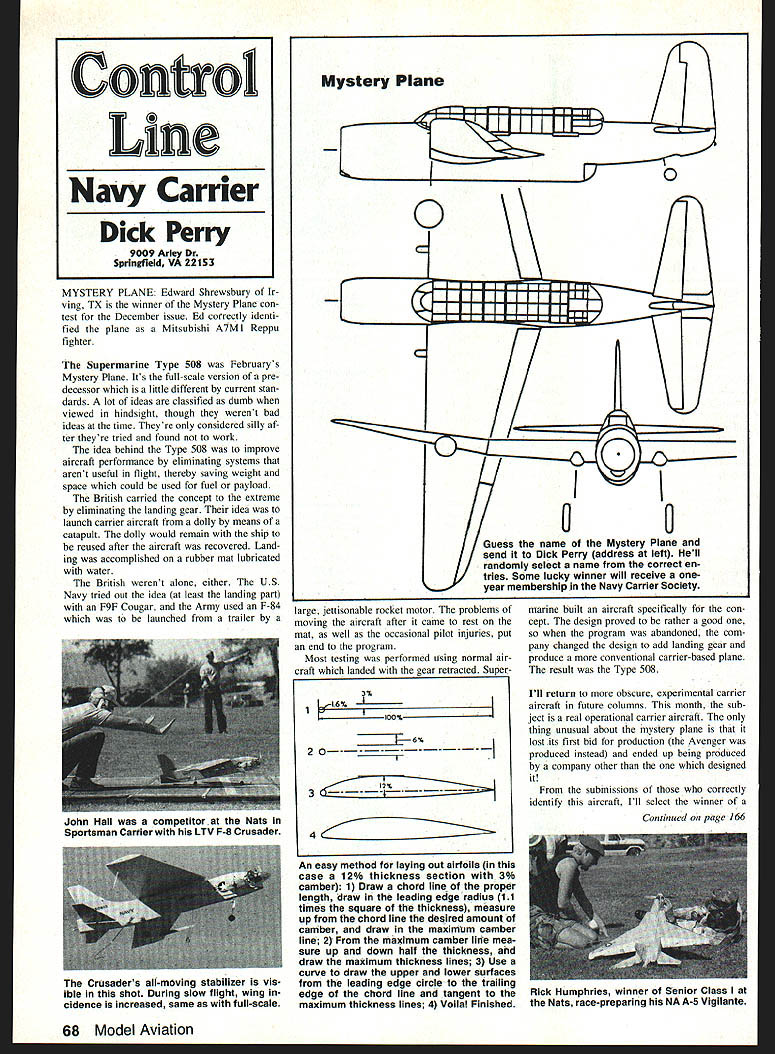
Mystery Plane
Edward Shrewsbury of Irving, TX is the winner of the Mystery Plane contest for the December issue. Ed correctly identified the plane as a Mitsubishi A7M1 Reppu fighter.
The Supermarine Type 508 was February's Mystery Plane. It's the full-scale version of a predecessor which is a little different by current standards. A lot of ideas are classified as dumb when viewed in hindsight, though they weren't bad ideas at the time. They're only considered silly after they're tried and found not to work.
The idea behind the Type 508 was to improve aircraft performance by eliminating systems that aren't useful in flight, thereby saving weight and space which could be used for fuel or payload.
The British carried the concept to the extreme by eliminating the landing gear. Their idea was to launch carrier aircraft from a dolly by means of a catapult. The dolly would remain with the ship to be reused after the aircraft was recovered. Landing was accomplished on a rubber mat lubricated with water.
The British weren't alone. The U.S. Navy tried the idea (at least the landing part) with an F9F Cougar, and the Army used an F-84 which was to be launched from a trailer by a large, jettisonable rocket motor. The problems of moving the aircraft after it came to rest on the mat, as well as the occasional pilot injuries, put an end to the program.
Most testing was performed using normal aircraft which landed with the gear retracted. Supermarine built an aircraft specifically for the concept. The design proved to be rather good, so when the program was abandoned the company changed the design to add landing gear and produce a more conventional carrier-based plane. The result was the Type 508.
I'll return to more obscure, experimental carrier aircraft in future columns. This month, the subject is a real operational carrier aircraft. The only thing unusual about the mystery plane is that it lost its first bid for production (the Avenger was produced instead) and ended up being produced by a company other than the one which designed it.
An easy method for laying out airfoils
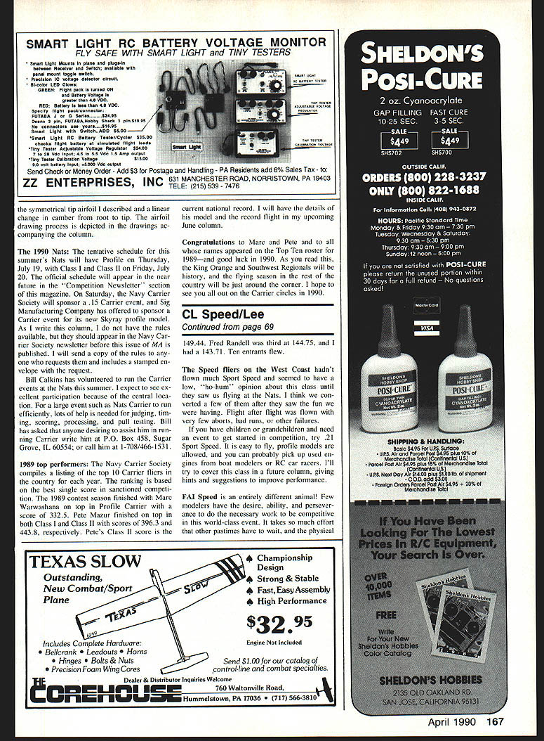
An easy method for laying out airfoils (in this case a 12% thickness section with 3% camber):
- Draw a chord line of the proper length; draw in the leading edge circle (radius = 1.1 times the square of the thickness, NACA formula), measure up from the chord line the desired amount of camber, and draw the maximum camber line.
- From the maximum camber line measure up and down half the thickness, and draw the maximum thickness lines.
- Use a curve to draw the upper and lower surfaces from the leading edge circle to the trailing edge of the chord line and tangent to the maximum thickness lines.
- Voila! Finished.
Airfoil selection
Occasionally I receive questions about airfoils best used for carrier models. Unlike the free-flight/glider fraternity, which has considerable information on airfoil performance at relatively low Reynolds numbers, carrier modelers have little experimental data to guide us. Most original information on airfoil sections was compiled by the National Advisory Committee for Aeronautics (NACA) for Reynolds numbers appropriate for full-size aircraft. What little information is available on airfoils of interest to us leads to some general conclusions, if not specific recommendations.
The general guidelines I use are:
- Airfoils on built-up wings should be about 9–12% thick.
- Solid wings should be thinner (as thin as 5% to save weight).
- They should have round leading edges (1.1 times the square of the thickness using the NACA formula).
Thus, a 12%-thick airfoil should have a leading edge radius of about 1.6% of the chord; i.e., a 12%-thick wing section with an 8-inch chord would be 0.96 inch thick with a leading edge radius of about 0.13 inch.
Exact airfoil shapes are not critical as long as both upper and lower surfaces have smooth contours. I've found that drafting curves are as good as airfoil tables for plotting sections. Unless a lot of extra time and effort go into the building process, the finished wing section won't be an accurate representation of what was planned.
Observation of models used in the Carrier events shows that most Class I and Class II models use cambered airfoils, and most Profile models use symmetrical sections. There are some notable—and highly successful—Profile exceptions. Bill Melton's Guardian, Harry Higley's Mo-Ho and Carrier Pigeon, and Carlos Aloise's Condor designs were quite successful, and all used cambered airfoils.
In general, a cambered airfoil will have minimum drag when it is flying at zero angle of attack. That means that a thin throat on the leading and trailing edges is lined up with the airflow. A properly designed Carrier wing has just enough camber to produce the needed lift for the airplane's weight and speed when it is near zero incidence.
The exact camber required will depend upon weight, wing area, speed, altitude, temperature, Reynolds number, and a few other factors. For typical Carrier models a tolerable stall deviation and a minimum-drag section is fairly consistent for most Carrier models. Large, light profiles are at one end of the spectrum, and small, heavy Class I and II ships are at the other end.
Another factor to consider is that drag can be reduced if lift smoothly drops to zero at the tip. This can't happen in a rectangular wing with constant airfoil section and constant incidence. A tapered or elliptic wing works rather well; I design my wings so that the tip is usually a little reflex and flying at zero incidence when trimmed to the speed. This reduces tip stalling.
Some people like to fly as close to the maximum allowable height (20 ft.) as they can. The idea is that the model flies a smaller circle, and therefore earns a greater high-speed score—even though the actual speed is the same as at a lower height. It doesn't work. The energy consumed climbing to the greater height lowers the time and the extra lift required slows the top speed. The increased lift depends upon speed, but on models of about 2 ft. wingspan it requires 3.5 to 5 times the lift of normal flight at 5 ft. For any typical Carrier model tested, the losses exceed the anticipated gain from flying at a shorter circle.
I try to fly a height of 5 ft. (I try to design my planes that way, too), but most of us are more comfortable flying at about 10 ft. At that height the typical Profile would need a root camber of about 2%. A typical Class II or III model would require a root camber of 3%. Those numbers are based on empirical experience and the flying characteristics I observe.
The 1990 Nats
The tentative schedule for this summer's Nats will have Profile on Thursday, July 19, with Class I and Class II on Friday, July 20. The official schedule will appear in the near future in the "Competition Newsletter" section of this magazine. On Saturday, the Navy Carrier Society will sponsor a 1/5 Carrier event, and Sig Manufacturing Company has offered to sponsor a Carrier event for its new Skyray profile model. As I write this column I do not have the rules available, but they should appear in the Navy Carrier Society newsletter before this issue of MA is published. I will send a copy of the rules to anyone who requests them and includes a stamped envelope with the request.
Bill Calkins has volunteered to run the Carrier events at the Nats this summer. I expect to see excellent participation because of the central location. For a large event such as Nats Carrier competition, lots of help is needed for judging, timing, scoring, processing, and pull testing. Bill has asked that anyone desiring to assist him in running Carrier write him at:
Bill Calkins P.O. Box 458 Sugar Grove, IL 60554
or call him at 1-708-466-1531.
1989 top performers
The Navy Carrier Society compiles a listing of the top 10 Carrier fliers in the country for each year. The ranking is based on the best single score in a sanctioned competition. The 1989 contest season finished with:
- Marc Warrawashong — top in Profile Carrier with a score of 332.5.
- Pete Mazur — top in Class I with a score of 396.3, and top in Class II with a score of 443.8 (Pete's Class II score is the current national record).
I will have the details of his model and the record flight in my upcoming June column.
Congratulations to Marc and Pete and to all whose names appeared on the Top Ten roster for 1989—and good luck in 1990. As you read this, the King Orange and Southwest Regionals will be history, and the flying season in the rest of the country will just be around the corner. I hope to see you all out on the Carrier circles in 1990.
Transcribed from original scans by AI. Minor OCR errors may remain.

