
Control Line: Navy Carrier
By Dick Perry
9009 Arley Dr. Springfield, VA 22153
Mystery Plane
The winner of the February Mystery Plane contest is Steve Zink of Pine Castle, FL. Steve correctly identified the Supermarine Type 508. Several entrants thought the aircraft was the Supermarine Attacker. Differences include the 508's V-tail, two engines, and tricycle gear.
The Attacker is an excellent candidate for a Carrier model. It was a clean airplane with a circular fuselage cross section, large tail surfaces (like the high-powered piston aircraft that preceded it), and a conventional landing gear rather than the tricycle gear of most later carrier jets. Three-views for the Attacker appeared in the August 1978 "CL Navy Carrier" column.
I have not included a Mystery Plane this month so I can devote photo space to another topic. I will announce the winner of the April Mystery Plane contest and discuss that plane in the August column.
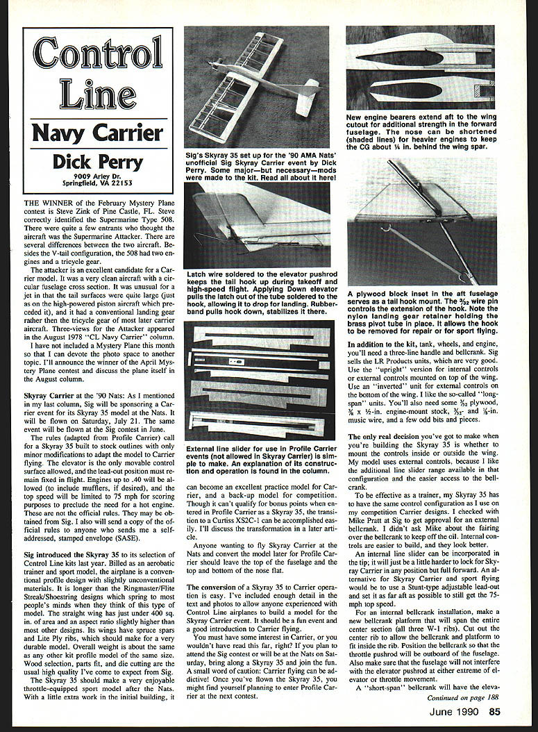
Skyray Carrier at the '90 Nats
Sig will sponsor a Carrier event for its Skyray 35 model at the Nats. The Skyray Carrier event will be flown Saturday, July 21; the same event will be flown at Sig's contest in June.
Rules (adapted from Profile Carrier)
- Skyray 35 must be built to stock outlines; only minor modifications to adapt the model for Carrier flying are allowed.
- The elevator is the only movable control surface permitted.
- The lead-out position must remain fixed during flight.
- Engines up to .40 cu in are allowed (mufflers included if desired).
- Top speed will be limited to 75 mph for scoring purposes (to preclude the need for a very hot engine).
- These are adapted rules; official rules may be obtained from Sig. Sig will send a copy of the official rules to anyone who sends a self-addressed, stamped envelope (SASE). I will also send a copy to anyone who sends me a SASE.
About the Skyray 35 kit
Sig introduced the Skyray 35 to its Control Line kit line as an aerobatic trainer and sport model. Key points:
- Conventional profile design with a straight wing.
- Wing area just under 400 sq. in.; aspect ratio slightly higher than some other designs.
- Wings use spruce spars and Lite Ply ribs for durability.
- Overall weight similar to other kit profile models of comparable size.
- Wood selection, parts fit, and die cutting are high quality.
With a little extra work during initial build, the Skyray 35 can become an excellent practice model for Carrier or a competition back-up. To allow later conversion to Profile Carrier (Curtiss XS2C-1 profile), leave the top of the fuselage and the top and bottom of the nose flat during initial construction.
Equipment and materials needed (in addition to kit)
- Fuel tank, wheels, and engine
- Three-line handle and bellcrank (Sig sells LR Products units)
- Use the upright version for internal controls or external controls mounted on top of the wing.
- Use the inverted version for external controls mounted on the bottom of the wing.
- 3/32-in. plywood (or 1/16-in. in some references for engine-mount stock depending on part)
- 3/8 x 1/2-in. engine-mount music wire (or 5/32-in. / 3/32-in. music wire for landing gear)
- A few small miscellaneous items (washers, tubing, spacers, etc.)
Conversion and Modifications for Carrier Operation
The conversion of a Skyray 35 to Carrier operation is straightforward. Below are recommended modifications and construction tips for experienced Control Line builders.
Controls: internal vs external bellcrank
You must choose whether to mount the bellcrank and controls inside or outside the wing.
- Internal controls
- Easier to build and better-looking.
- Internal line slider can be incorporated in the tip, though it is a little harder to lock for the Skyray Carrier position.
- For an internal bellcrank installation:
- Make a new bellcrank platform that spans the entire center section (all three W-1 ribs).
- Cut out the center rib to allow the bellcrank and platform to fit inside.
- Position the bellcrank so the throttle pushrod is outboard of the fuselage.
- Ensure the fuselage does not interfere with the elevator pushrod at either extreme of elevator or throttle movement.
- A short-span bellcrank will place the elevator pushrod on the outboard side of the fuselage; a long-span bellcrank will place it inboard and to the left side.
- Enlarge lead-out holes in the ribs as needed for clearance at extremes of control or line-slider movement.
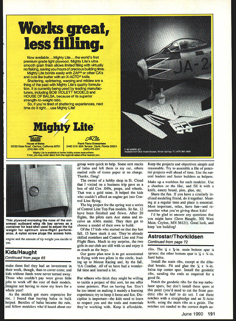
- External controls
- Provide additional line-slider range and easier access to the bellcrank.
- The author used external controls for better slider range; Sig approved the external bellcrank installation.
- For an external bellcrank installation:
- Add an extra rib and extend the center-section sheeting so the bellcrank is completely outboard of the fuselage.
- Simpler alternative: make the bellcrank mount from a rectangular piece of 3/32-in. plywood (1-1/2 x 5 in.) and integrate it with the wing sheeting immediately behind the spar. Cut the fuselage to make room for the bellcrank.
- Use washers or 1/32-in. plywood spacers under the bellcrank rather than cutting a slot in the mount for pivot-pin clearance—this prevents oil from getting inside the wing.
Alternative sport option: use a Stunt-type adjustable lead-out set placed as far aft as possible and still achieve the 75 mph top speed.
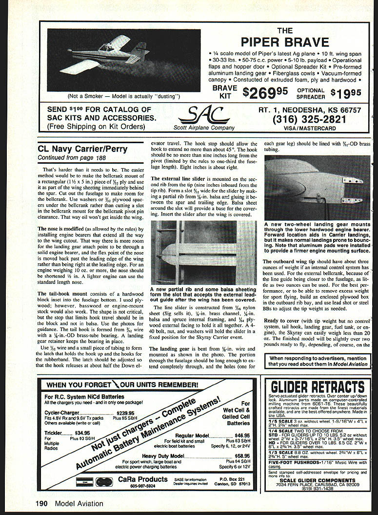
Nose and engine bearers
- Modify the nose by installing engine bearers that extend to the wing cutout. Benefits:
- More room for landing gear attachment through a solid engine bearer.
- Moves the flex point of the nose back past the wing leading edge (rather than at the leading edge).
- For engines weighing 10 oz or more, shorten the nose by 1/2 in. Lighter engines can use the standard nose length.
- Aluminum pads may be used to provide firmer engine-mounting surfaces.
Tail-hook mount and latch
- Tail-hook mount:
- Use a hardwood block inset into the fuselage bottom (plywood, basswood, or engine-mount stock are suitable).
- The stop that limits hook travel should be in the hardwood block, not in balsa.
- Tail hook:
- Formed from 1/8-in. wire with a 7/16-in. OD brass-tube bearing.
- A landing-gear retainer keeps the bearing in place.
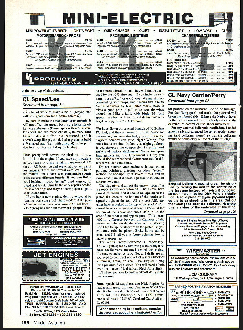
- Latch and rubberband hooks:
- Use 1/32-in. wire and a small piece of tubing to form the latch and the rubberband hooks.
- Adjust the latch so the hook releases at about half the down-elevator travel.
- The hook stop should allow the hook to extend no more than about 45°.
- Hook length should be no more than one-third of the fuselage length (rules). Typically, 8 in. from pivot is right; 9 in. is the maximum allowed.
External line slider and leadout guide
- Mount the external line slider on the second rib from the tip (about 9 in. inboard from the tip rib).
- Form a slot 5/8 in. wide for the slider:
- Make a partial rib from 1/32-in. balsa and glue it between the spar and the trailing edge.
- Sheet balsa around the slot to provide a base for the covering.
- Insert the slider after the wing is covered.
- Fabricate a new partial rib and add some balsa sheeting to form the slot that accepts the external leadout guide after covering.
- Line slider construction:
- Materials: 1/16-in. nylon sheet (Sig sells it), 1/8-in. brass channel, 3/16-in. balsa and spruce internal framing, and 1/4-in. plywood external facing.
- Use a 4-40 bolt, nut, and washers to hold the slider in a fixed position for the Skyray Carrier event.
Landing gear
- Bend landing gear from 5/32-in. wire and mount as shown in photos:
- The gear leg portion through the fuselage should extend completely through.
- Line the holes with 3/32-in. OD brass tubing.
- Two-wheel landing gear:
- Mounts through the lower hardwood engine bearer.
- A forward location helps Carrier landings but makes normal landings more prone to bouncing.
Tip weight and final weight
- Outboard wing tip weight:
- About 3 oz. if internal control system is used.
- About 2 oz. if external bellcrank and closer line guide are used.
- For adjustability, build an enclosed plywood box in the outboard rib bay and use lead shot or steel BBs to trim tip weight as needed.
- Typical weights:
- Ready-to-cover (with tip weight but no control system, tail hook, landing gear, fuel tank, or engine): easily less than 20 oz.
- Finished model: slightly over 20 oz., depending on engine used.
Final notes
- The Skyray 35 should make an enjoyable throttle-equipped sport model and, with modest modifications, a fine Carrier practice or competition back-up.
- Carrier flying can be addictive—once you try the Skyray 35 in Carrier you may find yourself planning to enter a Profile Carrier contest next season.
- If you plan to attend the Sig contest or the Nats on Saturday, bring a Skyray 35 and join the fun.
Transcribed from original scans by AI. Minor OCR errors may remain.

