
Navy Carrier
Richard L. Perry
THERE ARE many factors that contribute to a successful Carrier flight—pilot skill, engine performance, airplane, and weather. I rank them in that order. Under the 76-77 scoring system, pilot skill has replaced the engine as the most important factor. Without a good landing, it is hard to be competitive. Pilot skill also affects low speed and, to a lesser extent, high speed. The benefits of practice to improve low speed and landing scores are obvious. Practice also helps in achieving reliable and consistent engine performance.
Reading a magazine won't help improve pilot skills, and none of us can control the weather very effectively, so I'm not going to waste our time writing about these two factors. I am going to write about engines and airplanes in the next few months. The main goal of this series is to help the newcomer to Carrier flying avoid some of the frustration that the rest of us endured while we were starting out in the event. This month the topics are carburetors and fuel tanks with the emphasis on Profile Carrier.
Profile models must use a suction fuel system, of course, but since January 1976, we have had the option of using any style of carburetor that we desire. A lot has been said in various magazines about how to improve engine performance through proper break-in, proper fit of piston and shaft, proper timing, etc., but very little has been said about the carburetor. Most people are content to accept without question the standard carburetor that comes with the engine.
In most cases (the Fox Profile Carrier Special is an exception) stock RC carburetors are designed with small throat areas to provide good fuel draw and consistent engine runs under the widely varying flight loads and attitudes encountered in RC flying. In Carrier flying, our engines must cope with only two conditions that are critical for performance—takeoff and level flight at constant airspeed.
After takeoff, the high speed portion of the flight presents no problems in uneven fuel draw. The fuel is subjected to considerable centrifugal force, but this force is constant throughout the high speed portion of the flight. Under this condition, a small-throat carburetor with a high fuel draw is not needed as long as the fuel tank is appropriately positioned. The factor that determines the upper limit on carburetor throat area is the acceleration that occurs on takeoff. Carburetor throat area can be enlarged until the engine loses power on takeoff. (If your engine already has this problem, the difficulty may not be in the carburetor but in the fuel tank. Keep reading.)
Since it is difficult to back up to a smaller throat area after going too far, I will offer some suggestions based on my experience. I feel that a throat area of 22mm2 is a good compromise between power and sensitivity to fuel tank position. A 25mm2 intake can handle takeoff acceleration, but it is a little sensitive to fuel tank position. At 30mm2 some problems in acceleration occur, and fuel tank position is critical. To provide a reference, the Supertigre ST 35 RC has a throat area of 16mm2; the Fox Profile Carrier Special has a throat area of 29mm2.
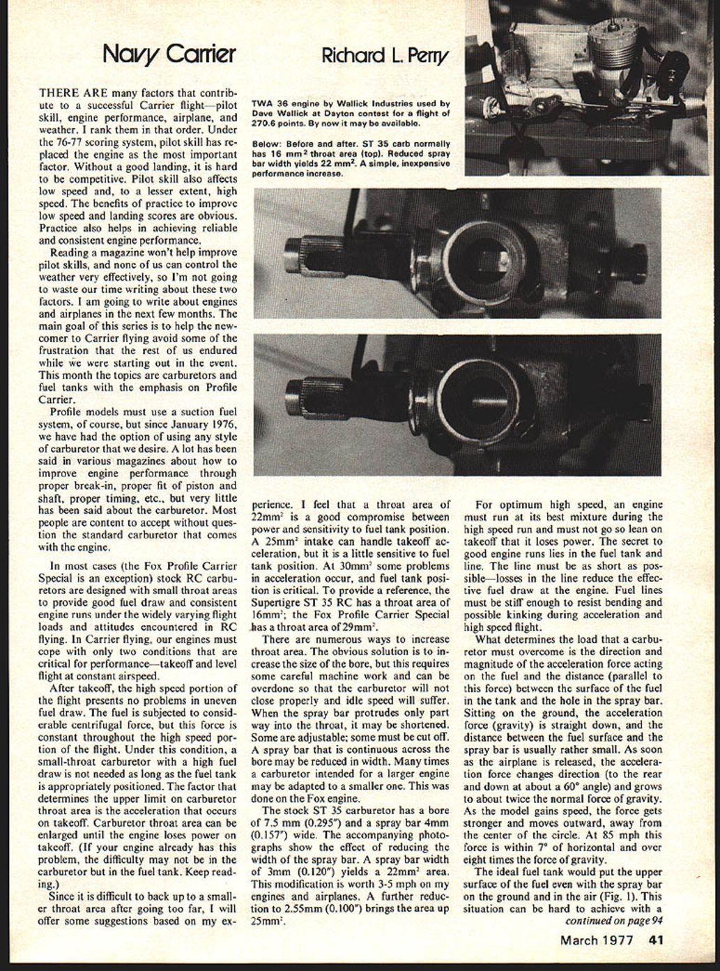
There are numerous ways to increase throat area. The obvious solution is to increase the size of the bore, but this requires some careful machine work and can be overdone so that the carburetor will not close properly and idle speed will suffer. When the spray bar protrudes only part way into the throat, it may be shortened. Some are adjustable; some must be cut off. A spray bar that is continuous across the bore may be reduced in width. Many times a carburetor intended for a larger engine may be adapted to a smaller one. This was done on the Fox engine.
The stock ST 35 carburetor has a bore of 7.5 mm (0.295") and a spray bar 4 mm (0.157") wide. The accompanying photographs show the effect of reducing the width of the spray bar. A spray bar width of 3 mm (0.120") yields a 22mm2 area. This modification is worth 3-5 mph on my engines and airplanes. A further reduction to 2.55 mm (0.100") brings the area up to 25mm2.
For optimum high speed, an engine must run at its best mixture during the high speed run and must not go so lean on takeoff that it loses power. The secret to good engine runs lies in the fuel tank and line. The line must be as short as possible—losses in the line reduce the effective fuel draw at the engine. Fuel lines must be stiff enough to resist bending and possible kinking during acceleration and high speed flight.
What determines the load that a carburetor must overcome is the direction and magnitude of the acceleration force acting on the fuel and the distance (parallel to this force) between the surface of the fuel in the tank and the hole in the spray bar. Sitting on the ground, the acceleration force (gravity) is straight down, and the distance between the fuel surface and the spray bar is usually rather small. As soon as the airplane is released, the acceleration force changes direction (to the rear and down at about a 60° angle) and grows to about twice the normal force of gravity. As the model gains speed, the force gets stronger and moves outward, away from the center of the circle. At 85 mph this force is within 7° of horizontal and over eight times the force of gravity.
The ideal fuel tank would put the upper surface of the fuel even with the spray bar on the ground and in the air (Fig. 1). This situation can be hard to achieve with a A standard Profile Carrier fuel tank mounting is fine unless the tank is only partially full. A half-full tank, however, increases the distance between fuel and spray bar on takeoff as the fuel goes to the back of the tank. The desired effect can be obtained by using a uniflow tank.
A uniflow tank has only one vent tube.
For the same mixture in the air and on the ground, fuel level should be even with the spray bar under both conditions.
The fuel level that the engine sees is the point at which the vent tube terminates within the tank (as long as the vent is immersed in fuel). A standard uniflow tank has the vent tube near the fuel pick-up point. This is not optimum for Carrier because this causes a greater apparent distance between the fuel and the carburetor during acceleration, and the apparent fuel level is often outboard of the carburetor for high speed.
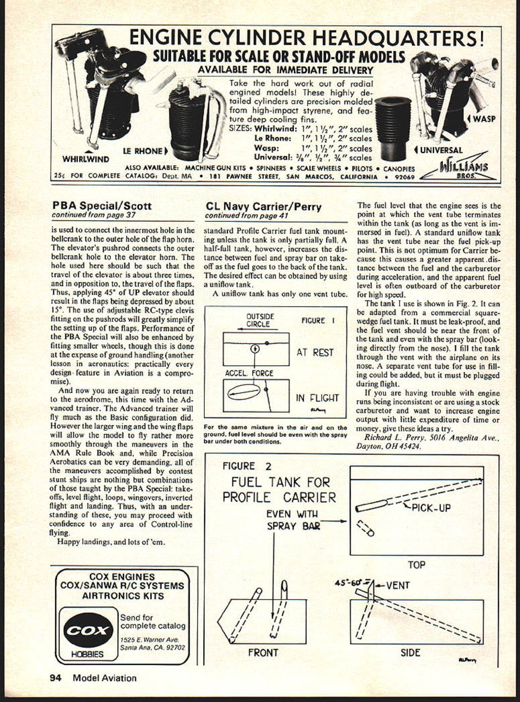
The tank I use is shown in Fig. 2. It can be adapted from a commercial square‑wedge fuel tank. It must be leak‑proof, and the fuel vent should be near the front of the tank and even with the spray bar (looking directly from the nose). I fill the tank through the vent with the airplane on its nose. A separate vent tube for use in filling could be added, but it must be plugged during flight.
If you are having trouble with engine runs being inconsistent or are using a stock carburetor and want to increase engine output with little expenditure of time or money, give these ideas a try.
Richard L. Perry, 5016 Angelita Ave., Dayton, OH 45424
FIGURE 2 FUEL TANK FOR PROFILE CARRIER
EVEN WITH SPRAY BAR
TOP PICK‑UP
FRONT
SIDE 45°–60° VENT
Transcribed from original scans by AI. Minor OCR errors may remain.

