

CONTROL LINE: NAVY CARRIER
Dick Perry 6739 Stonecutter Dr. Burke, VA 22015
Abstract
This month's column includes information on two engines (the O.S. .32F and the Webra Speed .32), some new construction ideas, and a sighting of a full-size Grumman Guardian.
MODIFICATIONS TO THE O.S. .32
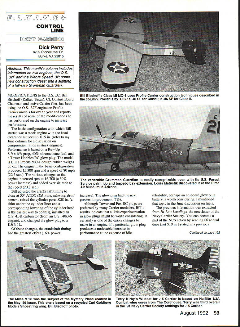
Bill Bischoff (Dallas, Texas), CL Contest Board Chairman and active Carrier flier, has been using the O.S. .32F engine on profile Carrier models for over a year and reports the results of several modifications he performed to increase performance.
Background and baseline
- Model: Bill's profile MO-1 design, weight 35 oz.
- Test conditions: Rev-Up 8½ × 6½ prop, 40% nitromethane fuel, Tower Hobbies RC glow plug.
- Engine basic configuration: stock engine with head clearance reduced to .015 in.
- Performance (basic): 15,300 rpm, speed ~80 mph (22.5 sec.).
Modifications and results
- After the changes, rpm increased to 16,700 (about a 9% power increase) and speed improved to about 86+ mph (20.8 sec.).
- Changes made:
- Adjusted crankshaft timing to close at 55° ATDC (after top dead center).
- Raised the cylinder ports .028 in. (a shim under the cylinder liner and corresponding lowering of the cylinder head is the easiest way to do this).
- Installed an O.S. 4BK carburetor (from an O.S. .40/.46 engine).
- Changed glow plug to a K&B 1L.
Effects of specific changes
- Crankshaft timing had the greatest effect (about a 16% power increase).
- Glow plug change produced the next-largest improvement (about 7%).
Notes on glow plugs and fuel
- Although Tower and Fox RC plugs are preferred by many Carrier modelers, Bill's results indicate that experimenting with glow plugs can be worthwhile — it's an easy change to try.
- If a glow plug improves peak performance but degrades idle reliability, consider using an on-board glow-plug battery.
- The previous information was extracted from Hi-Low Landings, the newsletter of the Navy Carrier Society. You can become part of the NCS by sending $6 annual dues to Bill Bischoff, 7550 Christie Lane, Dallas, TX 75249.
PROFILE-TYPE CONSTRUCTION IN CLASS I/II
Bill Bischoff also wrote and sent photos of his newest Class I/II model — another MO-1. Except for fuselage width (and adjusting dimensions to comply with the 5% tolerance required for Class I and II), the model is very similar to Bill's profile Carrier MO-1. The model spans 43¾ in. and weighs 44 oz. It is performing very well in Class I, and Bill thinks it has record potential.
Model description and controls
- Controls are mounted under the wing inboard of the fuselage (techniques more common to profile models than to usual Class I/II craft).
- The line slider is external.
- Pushrod runs along the outside of the fuselage to an exposed elevator horn.
- Throttle is operated by a torque tube formed using metal tubing and RC nose-gear steering arms.
- The torque tube carries the throttle linkage from the bellcrank side to the opposite side where the side-mounted engine's carburetor is located.
- The tail hook is mounted on the left side of the fuselage, similar to a profile Carrier model.
- The only internal hardware is the line-slider release cable, which is enclosed in the fuselage and wing for part of its run.
Wing construction
- The model uses a foam wing without balsa leading/trailing edges or sheeting.
- To stiffen the foam wing, Bill uses a Combat-model technique credited to Pat Willcox (Houston, Texas):
- Attach 1-inch-wide strips of water-dampened silkspan to the leading and trailing edges using a 50/50 solution of water and white glue (or aliphatic resin glue such as Titebond).
- The trailing edge first gets a narrow strip of Kevlar for additional strength (heavy thread will also suffice).
- Wing tips are covered with separate silkspan pieces on top and bottom, overlapping the leading and trailing-edge pieces.
- Apply a second coat of the glue/water mixture, then light-sand with 220-grit sandpaper when dry. If sanding through the glue or if silkspan gets fuzzy, add another coat of glue.
- Using aliphatic resin glue enhances adhesion of heat-applied covering film because the glue gets tacky when heated the first time.
- The process took Bill about two hours and added very little weight, while significantly improving wing stiffness and resistance to twisting.
Fuel tank and engine feeding
- The fuel tank is fully enclosed in the fuselage. The O.S. .40 SF engine operates on suction fuel feed.
- Location of the fuel tank inboard of the carburetor caused the engine to run rich in flight. Bill solved this by installing a Perry (no relation) oscillating pump.
Possible alternative solutions to a fuel-rich condition when the tank is inboard
- Mount the engine with the cylinder pointing inboard (toward the circle). This can eliminate the need for a throttle-linkage carry-through; it may require a bit of wingtip weight to balance the inboard-pointing cylinder.
- Install a tank extension outboard through the fuselage side (diameter at least 1/2 in.) so the tank's uniflow vent is positioned outboard of the carburetor, fooling the engine into acting as if the tank had been moved outboard.
- Allow the fuel tank to extend through the fuselage side or even mount the tank outside the fuselage. This may seem unorthodox for Class I/II, but protruding accessories (tail hook, control horns, lead-outs, pushrods, line guides, bellcranks, fuel lines, fillers, etc.) do not affect bounce points; fuel tanks should be similar. Comments welcome.
WEBRA SPEED .32
I recently received a Webra Speed .32 RC ABCD engine from Hobby Dynamics for evaluation. The ABCD designation refers to the piston/sleeve (ABC) combination with a Dykes piston ring (D) added.
So far I have only inspected and measured the Webra. It appears very well made, showing typical German craftsmanship throughout, and it features an interesting Dynamix slide-valve carburetor. Running it is next; I will have a full report in a future column.
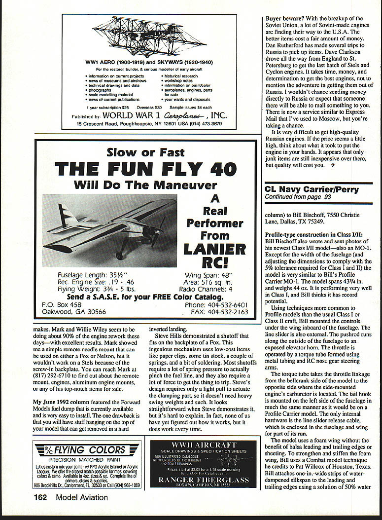
A GUARDIAN ON DISPLAY
Louis Matusik (St. Louis, Missouri) sent photos and information on a Grumman AF-2S Guardian he found at the Pima Air Museum in Tucson, Arizona. The Guardian, once a dominant model subject in CL Navy Carrier competition because of its availability as a Sterling kit, is on display in the condition in which it was acquired. It had been retired from the Forest Service where it was used as a fire bomber; the torpedo bay was slightly enlarged to hold tanks for fire retardant, and its colors reflect its service fighting forest fires rather than anti-submarine duty. Otherwise, it appears to be an excellent example of the Guardian.
I don't know how many Guardians remain, but there can't be very many. This is the only one I am aware of either on display or flying. Guardian lovers might stop by and give it a pat during travels through Arizona.
The Pima Air Museum is an outstanding museum and well worth a visit. It is located south of Davis-Monthan Air Force Base. Information may be obtained by writing or calling:
- Tucson Air Museum Foundation, 6000 East Valencia, Tucson, AZ 85706
- Telephone: (605) 574-9658
Transcribed from original scans by AI. Minor OCR errors may remain.

