
Control Line: Navy Carrier
Dick Perry, 31010 East Sunset Dr. North, Redlands, CA 92373-7453
Synopsis: You get to read a lot of opinions this month—about rules proposals and AMA officials. If you don't want to put up with my editorializing, skip to the section about movable wing tip weights. There's also a brief look back at CL flying over 30 years ago.
CARRIER rules proposals
We are blessed with the prospect of Navy Carrier rules remaining stable at least until 1996. The rules proposals published in summary form in the January issue included only one proposal affecting the Navy Carrier events. In case you didn't see it, don't be concerned about your eyesight failing—it wasn't identified as a carrier rules change in the heading. The proposal is CL-94-4, which was listed as affecting events 301–310 (Speed).
The proposal does not affect how the carrier events will be run; it changes only the procedures for establishing records in the three official Navy Carrier events. Existing rules allow records to be established only in class AA or higher contests. The new proposal, submitted by David Williams and endorsed by Carlos Aloise and Joe Brownlee, would allow national records in speed and carrier events to be established at class A contests.
The rationale supporting the proposed change is that special-interest groups find it increasingly hard to arrange contests having two events (AA contests must have four sets of awards through two places and include at least two rule-book events). A class A contest requires only that a single AMA rule-book event be offered.
Personally, I find the rationale a little hard to believe. Since both speed and Navy Carrier have multiple classes (three in carrier and nine in speed), it seems that almost any carrier or speed contest offering at least two awards in each event would qualify as an AA contest. It is common practice to offer .15 Carrier, to split Profile into Expert and Sportsman classes, or to offer a separate Junior–Senior Profile Carrier event. Even with combined Class I and II, it isn't exactly challenging to come up with an AA sanction.
Even if the proposal passes—and I see no reason to support it—we will see stable rules for the carrier events themselves for the next four years. Rules instability has been a commonly voiced reason for declining carrier participation in areas where nonparticipation is a problem. (It certainly isn't a problem in Texas!) Rules can't get much more stable than they will be now. Let's get out and enjoy the situation!
Contest Director and AMA performance
Do we have a problem? Proposal CL-94-4 claims a precedent in that for three years Contest Directors have submitted record applications resulting from flights at class A contests, and that AMA has approved those applications.
This statement raises a question of integrity or competence for the offending Contest Directors and forces one to question the actions of AMA Headquarters staff or CL Contest Board personnel.
There have been problems in AMA staff in the past, but I thought we were over most of them. The record application form revised in 1988 added a blank for the Contest Director to list the contest classification. It should not be that hard to look at that block. Records must be homologated (ratified) by the appropriate contest board. One must wonder if that is occurring, for surely the CL Contest Board chairman would catch such an error when he reviewed the application.
Changing the rules doesn't solve an integrity problem; prior actions were still violations. The way to solve such problems is to discipline the offenders. If one is to believe the proposer, Contest Directors are either lying on the record applications, or they are failing to follow the AMA rules. In either case, the offending CDs deserve to have their licenses revoked.
I've said my piece. Now it's your turn.
Movable wing tip weights
In previous columns I've discussed problems associated with the comparatively large amounts of wing tip weight required for good slow-flight performance. The important term here is "comparatively." Often you need a little more tip weight than necessary to balance the weight of the lines exactly. The increased weight improves line tension at the low speeds currently being flown. Too much weight can introduce instability, however, and should be avoided. Adjustable tip weight is a good feature to include on a model to allow for tuning the low-speed handling qualities.
The problem with using more wing tip weight than required to balance line weight is that the model yaws toward the outside of the circle during takeoff and initial acceleration. Basically, it is the same effect we try to produce during nose-high slow flight, only on a horizontal plane. Because the model's center of gravity is outboard from the thrust line, engine thrust rotates the model around the vertical axis, and the nose swings out. As speed picks up and acceleration slows, line tension overcomes the inertial effects of the wing tip weight, and the model resumes a more appropriate yaw angle relative to the direction of flight. The greater the wing tip weight, the greater the yaw effect.
The yaw reduces performance for three reasons:
- Increased drag (the fuselage isn't pointed into the relative wind, and the wheels aren't aligned with the direction the model is traveling).
- Reduced propeller efficiency (the propeller isn't aligned with the relative wind).
- Wasted thrust (the thrust produced by the propeller isn't aligned with the direction the model is traveling; part of the thrust is wasted in pulling on the lines).
The end result is reduced acceleration, and acceleration is critical for good high-speed performance. The effect is not great, but it seemed enough for me to work on a solution.
There have been attempts to solve this problem before. Many have been successful. It is a rather simple matter to put a sliding weight inside a tube. The weight is held near the fuselage at the start of the flight and is released sometime prior to slow flight.
When it is released, the weight slides through the tube to the end of the wing because of centripetal acceleration acting on the model. Although the concept is simple, the release becomes more complex.
The release mechanism adds weight and complexity. The tube also adds weight, and weight increases can hinder acceleration. Because the tube can add bending and torsional rigidity to the wing, it should be possible to reduce the weight of the outboard wing structure to compensate for the tube and release mechanism.
Because of the mass involved, a way must be found to slow the weight before it reaches the end of the tube. If you don't, the weight may not stop when it reaches the wing tip. It didn't happen to me, but I heard about it from a reliable source. No one was injured, fortunately. A spring in the end of the tube is one way to cushion the impact and preserve the structural integrity of the wing.
The sliding-weight scheme described above works very well, but it adds complexity. The sliding weight can't be adjusted to trim the model for slow flight. I wanted a system as easy to adjust as the weight boxes and lead-shot installations I've described in previous columns. I also wanted a system that was easy to construct and automatic in operation.
Almost all of the objectives were achieved. The system isn't completely automatic; the weight must be reset before flight. All that is required, however, is to hold the wing vertical with the outboard tip up and gently shake the model for about 10 seconds. I consider it a success.
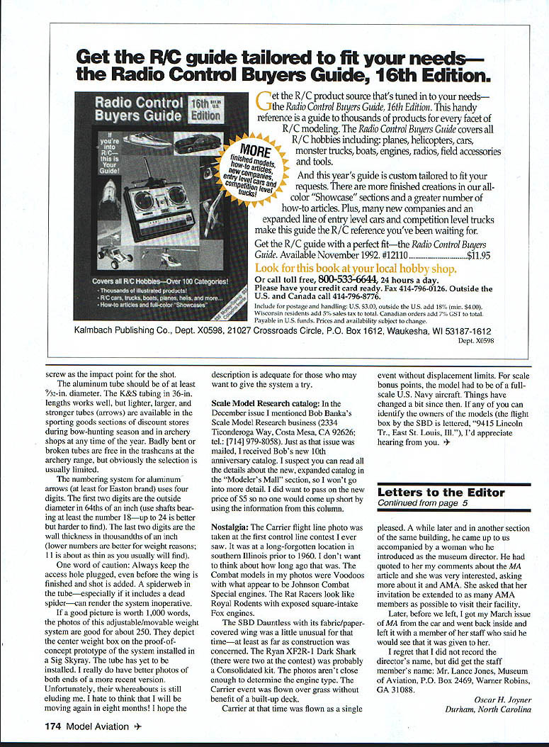
The system uses lead shot for the movable weight. The weight box in the wing tip is basically the same as those described previously. Another weight box is located at the center of the wing. A 1/4-inch-diameter nylon screw in one of the weight boxes serves as the plug through which the lead shot is added or removed to adjust the weight. A thin-wall aluminum tube connects the two weight boxes.
The tube enters the center box flush with the outboard side near the front of the box and high enough so the shot will be below the opening of the tube when the model is in its normal resting position. The outboard wall and floor of the center box are angled so the shot will roll toward the tube under the effects of the normal centripetal force encountered in flight.
Operation is simple. The shot starts out in the center box. When the model is released, the shot is forced to the rear of the center box by the model's forward acceleration. The model tracks straight ahead because the tip weight is in the center section and not in the wing tip.
As forward acceleration slows and centripetal acceleration increases, the shot starts its migration toward the opening of the tube. When it gets there, it falls through the tube to the weight box in the wing tip. By the time high-speed flight is finished, all the shot is in the tip box where it performs its usual function during slow flight.
Number-nine shot (0.08-inch diameter) is the best choice because of its small size—it flows easier through the fill hole and through the internal tube. Each individual pellet also exerts less force when it hits bottom at the tip box. Because the shot is traveling about 30 mph when it completes its trip, there should be a piece of hardwood, aluminum, nylon, etc., in the tip box to absorb the energy of the shot without damage. I use the threaded nylon block that holds the access cover in place.
Scale Model Research catalog
In the December issue I mentioned Bob Banka's Scale Model Research business (2334 Ticonderoga Way, Costa Mesa, CA 92626; tel.: (714) 979-8058). Just as that issue was mailed, I received Bob's new 10th-anniversary catalog. I suspect you can read all the details about the new, expanded catalog in the "Modeler's Mall" section, so I won't go into more detail here. I did want to pass on the new price of $5 so no one would come up short by using the information from this column.
Nostalgia
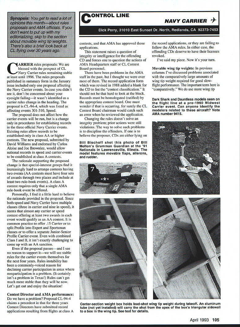
The Carrier flight-line photo was taken at the first control-line contest I ever saw. It was at a long-forgotten location in southern Illinois prior to 1960. I don't want to think about how long ago that was. The Combat models in my photos were Voodoos with what appear to be Johnson Combat Special engines. The Rat Racers look like Royal Rodents with exposed square-intake Fox engines.
The SBD Dauntless with its fabric/paper-covered wing was a little unusual for that time—at least as far as construction was concerned. The Ryan XF2R-1 Dark Shark (there were two at the contest) was probably a Consolidated kit. The photos aren't close enough to determine the engine type. The Carrier event was flown over grass without benefit of a built-up deck.
Carrier at that time was flown as a single event without displacement limits. For scale bonus points, the model had to be of a full-scale U.S. Navy aircraft. Things have changed a bit since then. If any of you can identify the owners of the models (the flight box by the SBD is lettered "9415 Lincoln Tr., East St. Louis, Ill."), I'd appreciate hearing from you.
Transcribed from original scans by AI. Minor OCR errors may remain.

