
Control Line: Racing
Bill Lee
IT SEEMS that there are many areas in construction and competition that can be best classified as black magic. It seems that every flier has his own way of doing something that is undoubtedly the "best" and the "only" way to do it. Well, I want to talk about a little theory and give some equations about fuel tanks, their shape, placement, and why they act the way they do when in flight. I hope that this will dispel some of the myth that surrounds this topic.
First of all, some basic facts. The weight of water is very near 1 oz. per fluid ounce.
This converts to .0346 pounds per cu. in. since one fluid ounce is 1.804 cu. in. O.K., so who's worried about the weight of water? Certainly, we use very little of it in flying model airplanes. Well, as it turns out, fuel is very near water in weight, .96 ounce per fluid ounce. So if we want to understand what goes on with a fuel system, we can investigate using water and know that we are in the ballpark for fuel. Listed below are some densities for various fluids.
Ounces/ fl. oz. Lbs./ cu. in. Specific Gravity Water 1.00 .0346 1.00 Methanol .81 .0281 .81 Ucon LB625 .96 .0332 .96 Nitromethane 1.06 .0368 1.06 Fuel (50% nitro) .96 .0332 .96
As can be seen from the table, alcohol is lighter than water, nitro is heavier, while oil is only slightly lighter. When you combine these components to make fuel, the result is only slightly lighter than water, about the same as the density of oil.
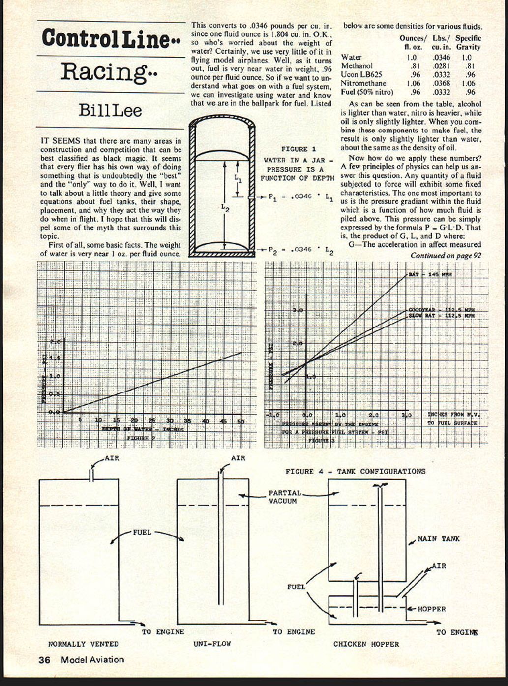
Now how do we apply these numbers? A few principles of physics can help us answer this question. Any quantity of a fluid subjected to force will exhibit some fixed characteristics. The one most important to us is the pressure gradient within the fluid which is a function of how much fluid is piled above. This pressure can be simply expressed by the formula P = G · L · D. That is, the product of G, L, and D where: in units of acceleration due to gravity.
L—Distance measured in inches from the free surface of the fluid to the point where the pressure is being measured, measured in the direction of the force which is causing the acceleration.
D—The density of the fluid measured in pounds per cubic inch.
What this formula tells us is, that as you pile up more and more fluid on top, the pressure we feel is correspondingly higher. In a model airplane these three variables are: G—loading due to centrifugal force as the plane flies in a circle; the density is that of fuel carried in the tank; and the distance, L, is the distance from the free surface of the fuel to the hole in the needle valve measured perpendicular to the line of flight. Fig. 1 illustrates this pressure as if we had a jar of water and we were measuring the pressure in the water at various levels in the jar. Note that the pressure exhibited is independent of the shape of the container, only on the three variables, G, L, and D.
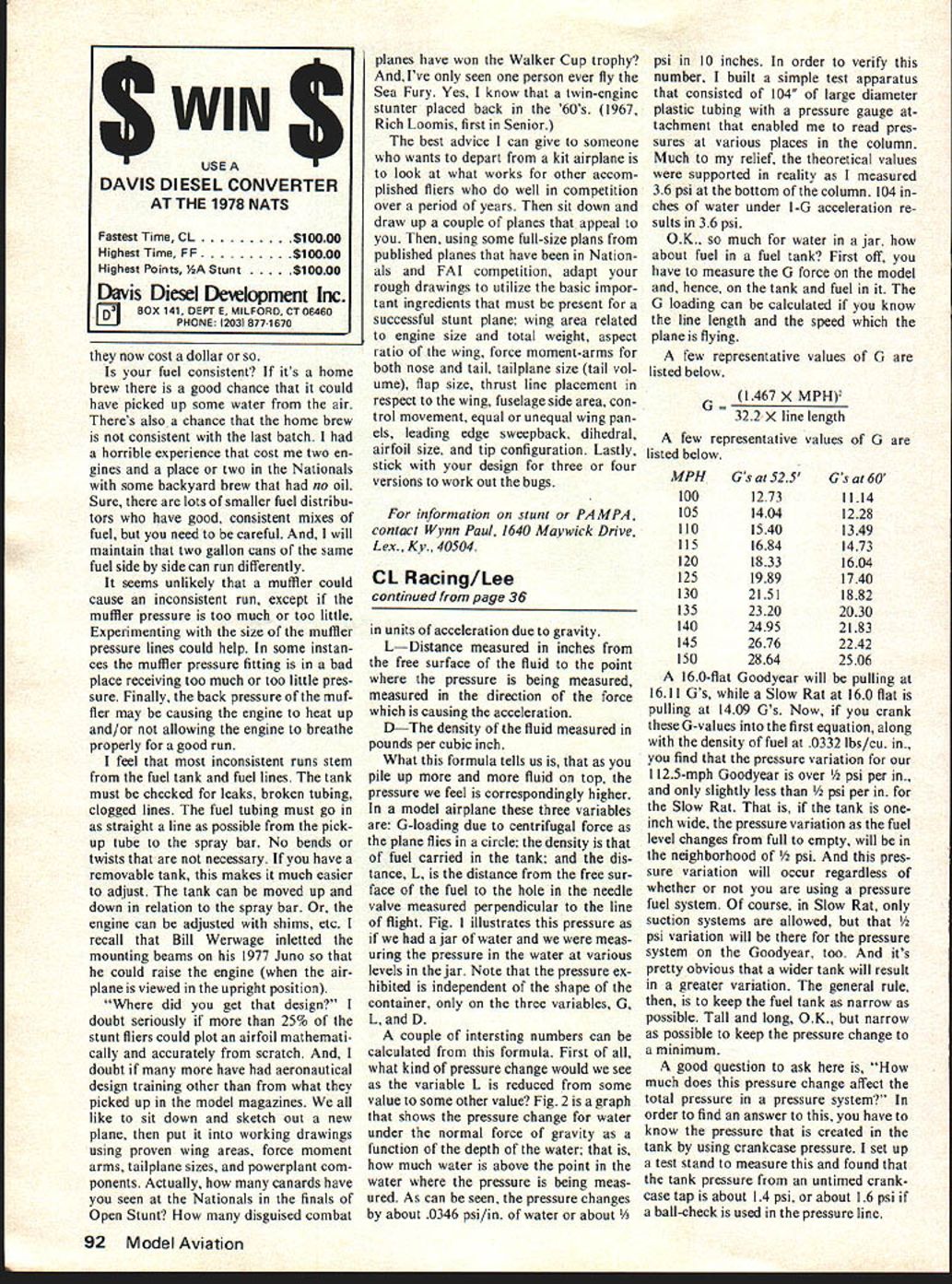
A couple of interesting numbers can be calculated from this formula. First of all, what kind of pressure change would we see as the variable L is reduced from some value to some other value? Fig. 2 is a graph that shows the pressure change for water under the normal force of gravity as a function of the depth of the water; that is, how much water is above the point in the water where the pressure is being measured. As can be seen, the pressure changes by about .0346 psi/in. of water or about 1/3 psi in 10 inches. In order to verify this number, I built a simple test apparatus that consisted of 10'4" of large diameter plastic tubing with a pressure gauge attachment that enabled me to read pressures at various places in the column. Much to my relief, the theoretical values were supported in reality as I measured 3.6 psi at the bottom of the column. 104 inches of water under 1-G acceleration results in 3.6 psi.
O.K., so much for water in a jar, how about fuel in a fuel tank? First off, you have to measure the G force on the model and, hence, on the tank and fuel in it. G loading can be calculated if you know the line length and the speed which the plane is flying.
A few representative values of G are listed below.
G = (1.467 X MPH)^2 32.2 X line length
MPH G's at 52.5' G's at 60' 100 12.73 11.14 105 14.04 12.28 110 15.40 13.49 115 16.84 14.73 120 18.34 16.04 125 19.99 17.40 130 21.51 18.82 135 23.20 20.30 140 24.96 21.83 145 26.73 22.42 150 28.64 25.06
A 16.0-flat Goodyear will be pulling at 16.11 G's, while a Slow Rat at 16.0 flat is pulling at 14.09 G's. Now, if you crank these G-values into the first equation, along with the density of fuel at .0332 lbs./cu. in., you find that the pressure variation for our 112.5-mph Goodyear is over 1/2 psi per in., and only slightly less than 1/2 psi per in. for the Slow Rat. That is, if the tank is one inch wide, the pressure variation as the fuel level changes from full to empty will be in the neighborhood of 1/2 psi. And this pressure variation will occur regardless of whether or not you are using a pressure fuel system. Of course, in Slow Rat, only suction systems are allowed, but that 1/2 psi variation will be there for the pressure system on the Goodyear, too. And it's pretty obvious that a wider tank will result in a greater variation. The general rule, then, is to keep the fuel tank as narrow as possible. Tall and long, O.K., but narrow as possible to keep the pressure change to a minimum.
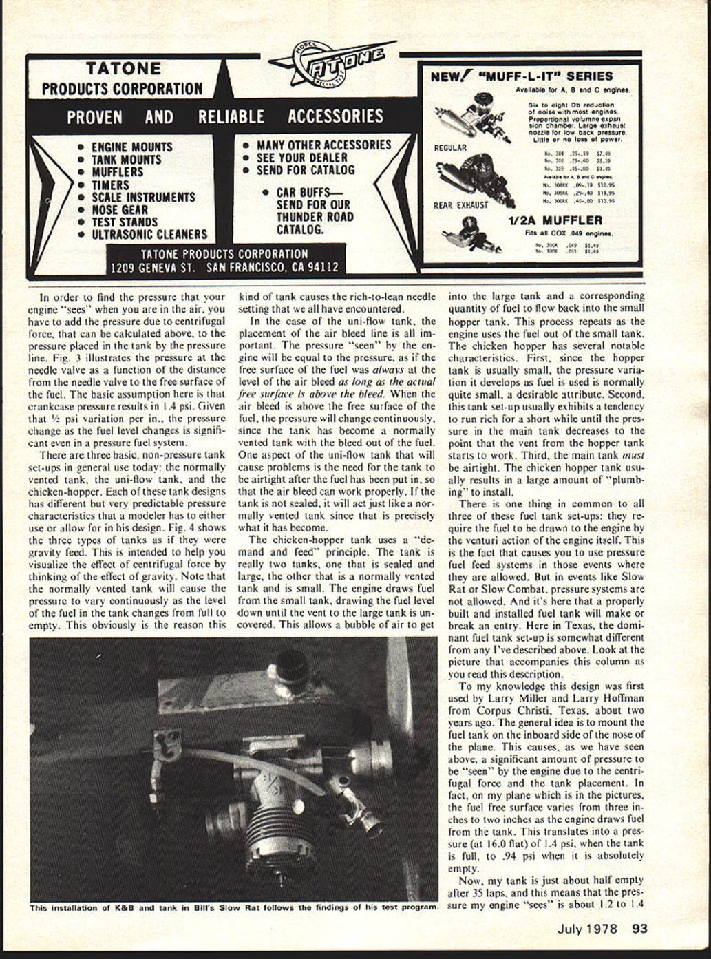
A good question to ask here is, "How much does the pressure change affect the total pressure in a pressure system?" In order to find an answer to this, you have to know the pressure that is created in the tank by using crankcase pressure. I set up a test stand to measure this and found that the tank pressure from an un-timed crankcase tap is about .41 psi, or about 1.6 psi if a ball-check is used in the pressure line. There are three basic, non-pressure tank set-ups in general use today: the normally vented tank, the uni-flow tank, and the chicken-hopper. Each of these tank designs has different but very predictable pressure characteristics that a modeler has to either use or allow for in his design. Fig. 4 shows the three types of tanks as if they were gravity feed. This is intended to help you visualize the effect of centrifugal force by thinking of the effect of gravity. Note that the normally vented tank will cause the pressure to vary continuously as the level of the fuel in the tank changes from full to empty. This obviously is the reason this kind of tank causes the rich-to-lean needle setting that we all have encountered.
In the case of the uni-flow tank, the placement of the air bleed line is all important. The pressure "seen" by the engine will be equal to the pressure, as if the free surface of the fuel was always at the level of the air bleed as long as the actual free surface is above the bleed. When the air bleed is above the free surface of the fuel, the pressure will change continuously, since the tank has become a normally vented tank with the bleed out of the fuel. One aspect of the uni-flow tank that will cause problems is the need for the tank to be airtight after the fuel has been put in, so that the air bleed can work properly. If the tank is not sealed, it will act just like a normally vented tank since that is precisely what it has become.
The chicken-hopper tank uses a "demand and feed" principle. The tank is really two tanks, one that is sealed and large, the other that is a normally vented tank and is small. The engine draws fuel from the small tank, drawing the fuel level down until the vent to the large tank is uncovered. This allows a bubble of air to get into the large tank and a corresponding quantity of fuel to flow back into the small hopper tank. This process repeats as the engine uses the fuel out of the small tank. The chicken hopper has several notable characteristics. First, since the hopper tank is usually small, the pressure variation it develops as fuel is used is normally quite small, a desirable attribute. Second, this tank set-up usually exhibits a tendency to run rich for a short while until the pressure in the main tank decreases to the point that the vent from the hopper tank starts to work. Third, the main tank must be airtight. The chicken hopper tank usually results in a large amount of "plumbing" to install.
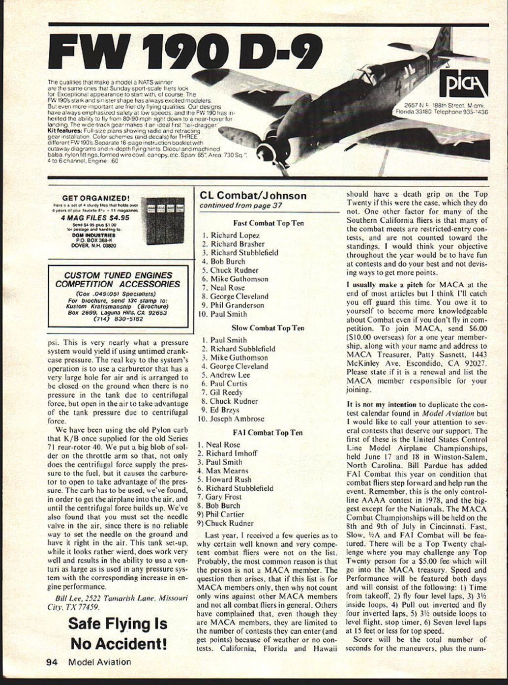
There is one thing in common to all three of these fuel tank set-ups: they require the fuel to be drawn to the engine by the venturi action of the engine itself. This is the fact that causes you to use pressure fuel feed systems in those events where they are allowed. But in events like Slow Rat or Slow Combat, pressure systems are not allowed. And it's here that a properly built and installed fuel tank will make or break an entry. Here in Texas, the dominant fuel tank set-up is somewhat different from any I've described above. Look at the picture that accompanies this column as you read this description.
To my knowledge this design was first used by Larry Miller and Larry Hoffman from Corpus Christi, Texas, about two years ago. The general idea is to mount the fuel tank on the inboard side of the nose of the plane. This causes, as we have seen above, a significant amount of pressure to be "seen" by the engine due to the centrifugal force and the tank placement. In fact, on my plane which is in the pictures, the fuel free surface varies from three inches to two inches as the engine draws fuel from the tank. This translates into a pressure (at 16.0 ft) of 1.4 psi when the tank is full, to .94 psi when it is absolutely empty.
Now, my tank is just about half empty after 35 laps, and this means that the pressure my engine "sees" is about 1.2 to 1.4 psi. This is very nearly what a pressure system would yield if using untimed crankcase pressure. The real key to the system's operation is to use a carburetor that has a very large hole for air and is arranged to be closed on the ground when there is no pressure in the tank due to centrifugal force, but open in the air to take advantage of the tank pressure due to centrifugal force.
We have been using the old Pylon carb that K/B once supplied for the old Series 71 rear-rotor .40. We put a big blob of solder on the throttle arm so that, not only does the centrifugal force supply the pressure to the fuel, but it causes the carburetor to open to take advantage of the pressure. The carb has to be used, we've found, in order to get the airplane into the air, and until the centrifugal force builds up. We've also found that you must set the needle valve in the air, since there is no reliable way to set the needle on the ground and have it right in the air. This tank set-up, while it looks rather weird, does work very well and results in the ability to use a venturi as large as is used in any pressure system with the corresponding increase in engine performance.
Bill Lee, 2522 Tamarisk Lane, Missouri City, TX 77459.
Transcribed from original scans by AI. Minor OCR errors may remain.

