
Control Line: Racing
Bill Lee
Introduction
Let's talk about forces — in particular, the forces which act on a racing model in flight. We will state a couple of laws of physics and then see how they apply to a model airplane in flight.
Newton's three laws (restated with examples)
- Motion at a constant velocity is the natural behavior of bodies.
- The force acting on a body is equal to the mass of the body times its acceleration (F = m·a).
- Whenever one object exerts a force on a second object, the second exerts an equal force in the opposite direction on the first.
Examples:
- When you start an object moving, it tends to keep moving, slowing only due to wind resistance, friction, etc. If no forces acted on it, a thrown ball would travel forever in a straight line.
- Newton's second law: a force applied to an object of mass m produces acceleration in the direction of the force. A model engine produces thrust that accelerates the airplane until resistive forces (drag) equal thrust; then the model reaches steady-state speed.
- A box sitting on the floor exerts a downward force equal to its weight; the floor pushes back with an equal and opposite force, so no net acceleration occurs.
Forces on a racing model
Consider an airplane in flight. The major forces acting on the plane are:
- Thrust (forward)
- Air resistance / drag (rearward)
- Gravity (downward)
- Lift (perpendicular to the wing surface)
If the plane is in steady (nonaccelerating) straight flight, the vector sum of these forces is zero: thrust equals drag, and lift equals weight.
Circular flight
Racing models fly in a circle, so they experience a turning force — the centripetal force — provided by the control lines. (The pilot at the handle feels the reaction as a centrifugal force.) In steady circular flight at constant speed and constant height (equal to handle height), the thrust and drag balance and we can analyze the lateral forces from the rear view.
Centripetal force:
- Fc = M·V^2 / R
- M = mass of the plane
- V = velocity (ft/s)
- R = radius from center of rotation to the plane (ft)
Centripetal acceleration (mass-independent):
- Ac = V^2 / R
Centripetal acceleration in Gs:
- Ac (Gs) = V^2 / (g·R) = V^2 / (32.2·R)
Alternate form using elapsed time:
- Ac (Gs) = 216447.2 / (T^2 · R)
- T = time to travel 1/2 mile (s)
- R = line length (ft)
Example:
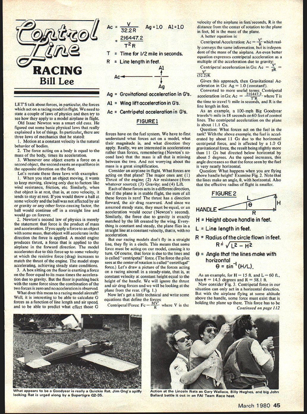
- A 100-mph Big Goodyear travels 1/2 mile in 18 seconds on 60 ft control lines. The centripetal acceleration on the plane is about 11.1 Gs.
Effects on fuel and the tank
Question: What forces act on the fuel in the tank?
- Using the example above, the fuel is accelerated by about 11 Gs horizontally (centripetal) and by 1 G vertically (gravity). The resultant vector is slightly more than 11 Gs and directed a few degrees below horizontal. At higher speeds the angle becomes even smaller, and the resultant force on the fuel is nearly horizontal.
Flying above handle height
When you fly above handle height the lines make an angle θ with the horizontal and the effective radius of flight is smaller. Refer to the figures (Fig. 2, Fig. 3) for geometry.
For the Big Goodyear example (θ = 14.5°):
- Ac = 11.5 Gs
- At = Ac · cos(14.5°) = 11.5 × 0.9681 = 11.1 Gs
- At = acceleration transmitted through the lines (horizontal component)
- Alt = Ac · sin(14.5°) = 11.5 × 0.25 = 2.9 Gs
- Alt = vertical component of centripetal acceleration the wing must handle
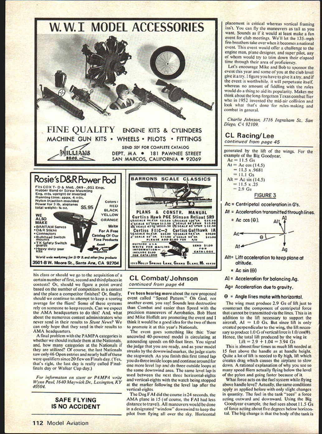
Figure notes (labels):
- Ac = Centripetal acceleration in Gs.
- At = Acceleration transmitted through lines.
- Alt = Lift acceleration to keep plane at altitude (vertical component).
- Ag = Acceleration due to gravity (1.0 G).
- θ = Angle the lines make with horizontal.
The wing must produce 2.9 Gs of lift just to counteract the vertical component of centripetal force that cannot be transmitted via the lines. This is in addition to the lift necessary to support the aircraft (Ag = 1.0 G). Because lift acts perpendicular to the wing, the magnitude of lift required to produce 1.0 G vertical force is about 1.04 G. Therefore the total lift produced by the wing is:
- Lift = 2.9 + 1.04 = 3.94 Gs
This is almost four times the lift needed at 15 feet above the handle compared with at handle height. Much more lift is needed to fly higher; that lift produces additional drag, which slows the airplane. This helps explain why many speed fliers fly below the top of the pylon and go faster because of it.
Fuel system effects above handle height
The fuel in the tank sees a force acting outward and downward. For the Big Goodyear example the fuel feels about 11.5 Gs acting about five degrees below horizontal. The change in attitude of the tank (tilting inboard by θ) can cause significant changes in fuel geometry and feed behavior if not accounted for.
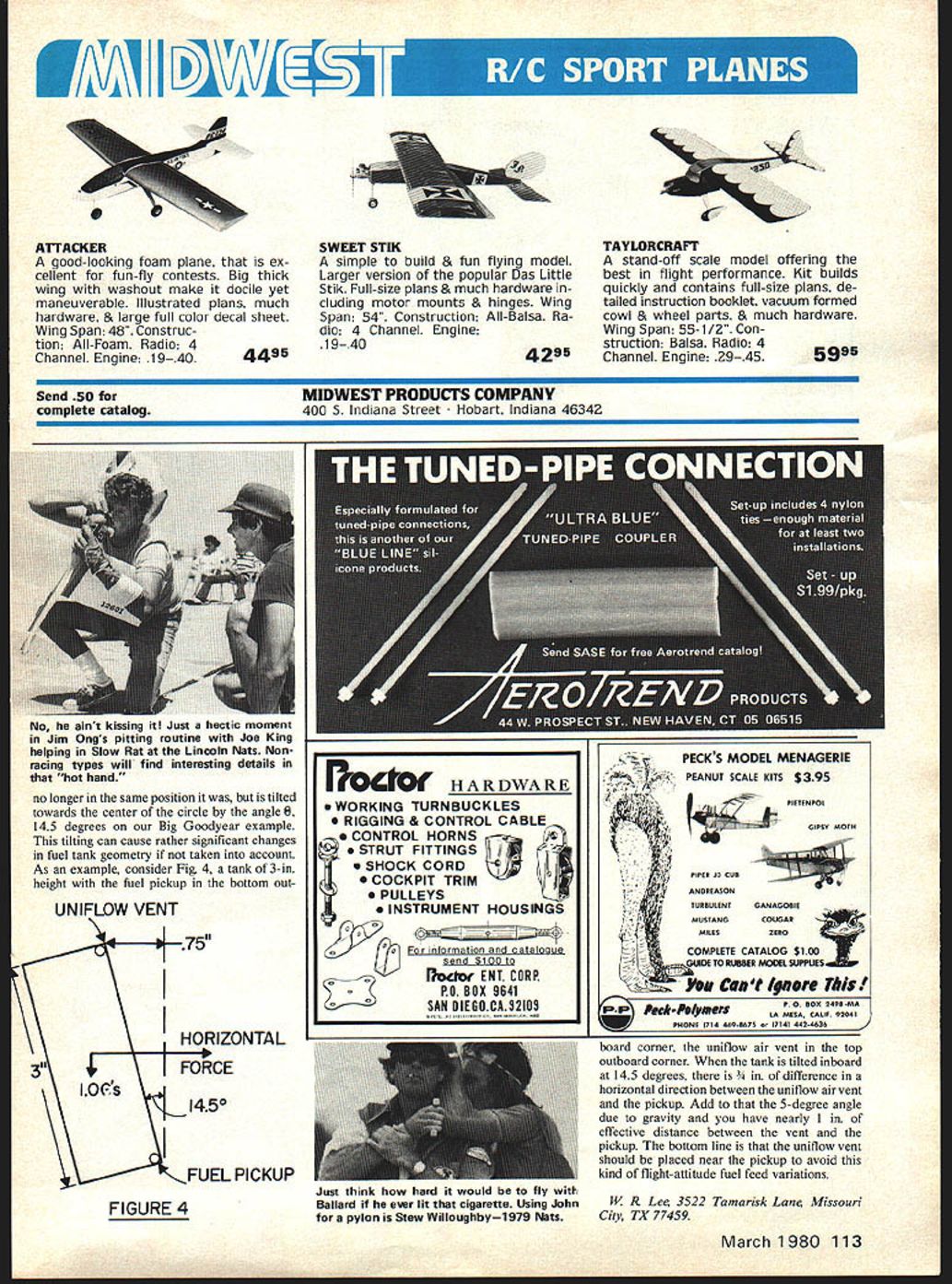
Example tank geometry (Fig. 4):
- Tank height: 3 in.
- Fuel pickup: bottom outboard corner
- Uniflow air vent: top outboard corner
When the tank tilts inboard by 14.5°, there is about 3/4 in. of horizontal difference between the vent and the pickup. Add the ~5° tilt due to the resultant G-vector and you have nearly 1 in. of effective distance between vent and pickup. To avoid feed problems caused by flight attitude, place the uniflow vent near the pickup.
Conclusion / Author
W. R. (Bill) Lee 3522 Tamarisk Lane Missouri City, TX 77459
Transcribed from original scans by AI. Minor OCR errors may remain.

