
Control Line: Racing
Bill Lee
It seems that some things we do in our racing setups are so "normal" that we forget just what it is we are doing. A case in point is the following information that I'm taking from a 1976 issue of the Duke City Dope Sheet, the club publication of the Albuquerque, NM Thunderbirds. This short article was originally authored by Phil Shew and is titled "Landing Gear Setup."
Landing Gear Setup (Phil Shew — quoted)
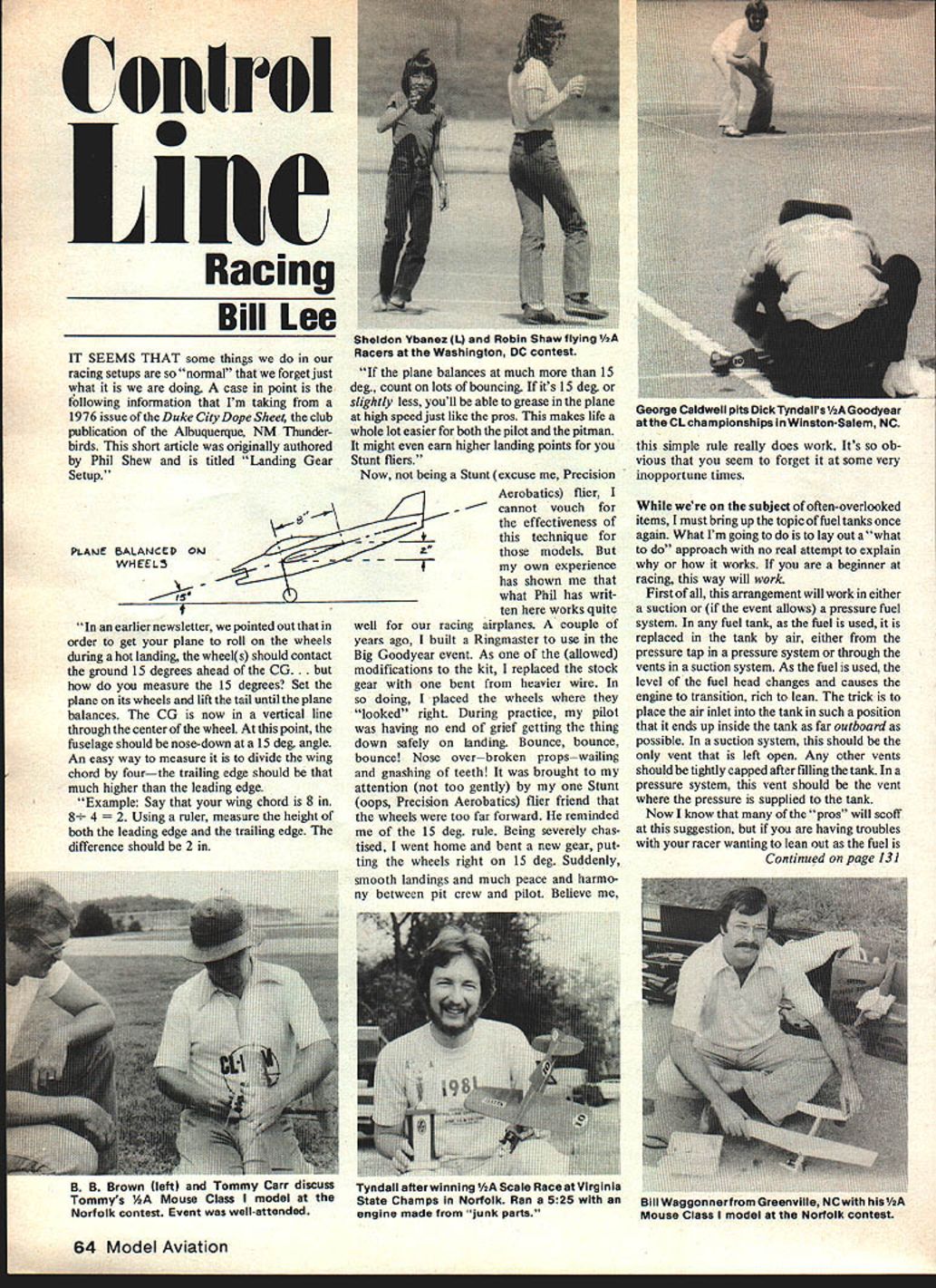
In an earlier newsletter, we pointed out that in order to get your plane to roll on the wheels during a hot landing, the wheel(s) should contact the ground 15 degrees ahead of the C.G. ... but how do you measure the 15 degrees? Set the plane on its wheels and lift the tail until the plane balances. The C.G. is now in a vertical line through the center of the wheel. At this point, the fuselage should be nose-down at a 15 deg. angle. An easy way to measure it is to divide the wing chord by four — the trailing edge should be that much higher than the leading edge.
Example:
- Say that your wing chord is 8 in. 8 ÷ 4 = 2.
- Using a ruler, measure the height of both the leading edge and the trailing edge.
- The difference should be 2 in.
If the plane balances at much more than 15 deg., count on lots of bouncing. If it's 15 deg. or slightly less, you'll be able to grease in the plane at high speed just like the pros. This makes life a whole lot easier for both the pilot and the pitman. It might even earn higher landing points for you Stunt fliers.
Author's experience with gear placement
Now, not being a Stunt (excuse me, Precision Aerobatics) flier, I cannot vouch for the effectiveness of this technique for those models. But my own experience has shown me that what Phil has written here works quite well for our racing airplanes.
A couple of years ago I built a Ringmaster to use in the Big Goodyear event. As one of the allowed modifications to the kit, I replaced the stock gear with one bent from heavier wire. In so doing, I placed the wheels where they "looked" right. During practice, my pilot was having no end of grief getting the thing down safely on landing: bounce, bounce, bounce! Nose over — broken props — wailing and gnashing of teeth! It was brought to my attention (not too gently) by my one Stunt (oops, Precision Aerobatics) flier friend that the wheels were too far forward. He reminded me of the 15 deg. rule. Being severely chastised, I went home and bent a new gear, putting the wheels right on 15 deg. Suddenly, smooth landings and much peace and harmony between pit crew and pilot. Believe me, this simple rule really does work. It's so obvious that you seem to forget it at some very inopportune times.
Fuel Tanks — a practical "what to do" approach
While we're on the subject of often-overlooked items, I must bring up the topic of fuel tanks once again. What I'm going to do is lay out a "what to do" approach with no real attempt to explain why or how it works. If you are a beginner at racing, this way will work.
First of all, this arrangement will work in either a suction or (if the event allows) a pressure fuel system. In any fuel tank, as the fuel is used, it is replaced in the tank by air, either from the pressure tap in a pressure system or through the vents in a suction system. As the fuel is used, the level of the fuel head changes and causes the engine to transition, rich to lean.
The trick is to place the air inlet into the tank in such a position that it ends up inside the tank as far outboard as possible.
- In a suction system, this should be the only vent that is left open. Any other vents should be tightly capped after filling the tank.
- In a pressure system, this vent should be the vent where the pressure is supplied to the tank.
Now I know that many of the "pros" will scoff at this suggestion, but if you are having troubles with your racer wanting to lean out as the fuel is used, give this suggestion a try. You might be surprised at the difference. Even some of the "pros" might want to try it.
TR info — engine cooling and related items (Walt Perkins)
Here's an interesting view on engine cooling and related items in TR that I'm borrowing from Walt Perkins, the father of Gator Tales and the driving force behind Shadow Racing. (If you want his stuff firsthand, contact Walt and get on his mailing list.)
Engine cooling has been a popular topic this year, and it seems there is a magic clearance dimension between the cylinder and cooling duct... but no one is quite sure what it is! Do I have an opinion? Sure... it's not critical.
For three years we have been using molded cooling ducts that were assembled right on the engine cylinder (the largest cylinder we own with a couple of layers of cellophane tape wrapped around it). After the model is flown we can always find evidence of the cylinder touching the duct somewhere... and we don't care. The duct has standard geometry (1/4-in. wide entry; 7/16-in. wide exit) and can easily be reproduced in balsa. We've used the same model to record approximately the same times in 45 deg. weather (Poland) and 110 deg. weather (Texas). It doesn't matter if we use an aluminum case or a magnesium case. In short, we don't worry much about cylinder cooling.
It is my opinion that a lot of the problems people are blaming on the engine or on "bad cooling" are actually caused by something else! To illustrate, here are two case histories:
- One modeler wrote that he couldn't get his mag engine to run "as well" on the same day as his aluminum case engine. Well, we can't either if all we do is swap engines... we have to adjust the tank position to counteract the change in center of gravity caused by the lighter motor! Some people will argue that the model flies at the same angle (tangentially) regardless of CG position, but I can tell you that we have to make a tank adjustment when we change engines.
- Another modeler wrote that his mag engine went like gangbusters in the early English spring but couldn't get out of its own way in the summer heat. Instead of looking for improved cylinder cooling, I suggested he consider better crankcase cooling. Magnesium and titanium have vastly different coefficients of thermal expansion; the construction that worked fine in the spring was providing enough cooling to keep the bearings happy, but warmer weather was not! I haven't heard back from this modeler yet as to what he thought of my suggestion, and I could be wrong, but that is what our experience has shown.
A dirty motor will also make you think you have other problems. A team on the West Coast recently chased after a good setting all weekend only to discover the real problem was a dirty motor. J. E. Albritton and I have spent our time in vain looking in the wrong area to solve a problem only to discover the real culprit was somewhere else. We learned the hard way, too!
Bill Lee 3522 Tamarisk Ln. Missouri City, TX 77459.
Transcribed from original scans by AI. Minor OCR errors may remain.

