
Control Line: Racing
John Ballard
Racing Fuel
I received a flurry of mail after my June column concerning racing fuels and the limiting of same in sanctioned contests. The majority of people had minor questions concerning blending in various "trick" ingredients they had heard would give them an extra margin of speed. I received a long-distance call from Vic Garner regarding my statement about stable fuel solutions using castor oil not being obtainable above approximately 30% nitro concentration. Vic reminded me of the days when he (and others) mixed the fuel with increased concentrations of nitro (without the nitrobenzene co-solvent) by warming it next to the radiator in their cars.
I can remember a couple of occasions during the old "King Orange" International contest where we had to keep the fuel warm continually because the oil was separating readily. I can also remember doing the same to cans of K&B speed fuel. As I recall, in those days they were using congealed soybean oil; it would float in wads to the surface, but if we warmed the can behind the radiator in our car or on the intake manifold, the fuel showed no incompatibility. Competitors in California (where K&B fuel is made) of course don't have to fly under the low-temperature conditions of the Midwest such as five to ten degrees below zero. Many times we've had competitions where the temperature was around 40° to 45° Fahrenheit, especially in the early spring months.
Low-nitro acceptance
I have attended four major regional racing competitions so far this summer, all of which utilized 10% nitro fuel in all racing events. The grumbling and vocal disagreement with the 10% nitro rule—as well as with the brand or composition of fuel supplies—has quieted considerably. Since all competitors must run from the same gallon jug, they all basically have the same problems.
One positive effect of the 10% nitro fuel is that it has brought back a few of the old engines which were discarded or set aside when the nitro went into the 60–70% range. The old K&B .40S for Rat Race has made an amazing comeback; this engine seems to perform extremely well on 10% nitro—much better than many of the present high-tech, high-nitro Rat engines. Several competitors have found they can run the Fox .15 in Scale Racing and be much more competitive, as long as the nitro is controlled at 10%.
I received my largest and most sophisticated written response after including Bill Lee's "summary of basic feelings" of the majority of control line racing competitors (interspersed with Bill's personal opinions) in the June issue. I had several letters from all geographical areas of control line racing activity, as well as from Australia and Canada. The majority are in agreement, but many questioned the sizable monetary investment in the .21 Rat engine for the average racing competitor.
Of the five control line racing competitions I have attended, the highest-participant event is Midwest Sport Race. This is very similar to the Southwest Sport Race and Northwest Sport Race in rules interpretation. In all five contests, no less than 30 competitors were entered in Sport Race, and they used a myriad of aircraft types with assorted engine/tank combinations.
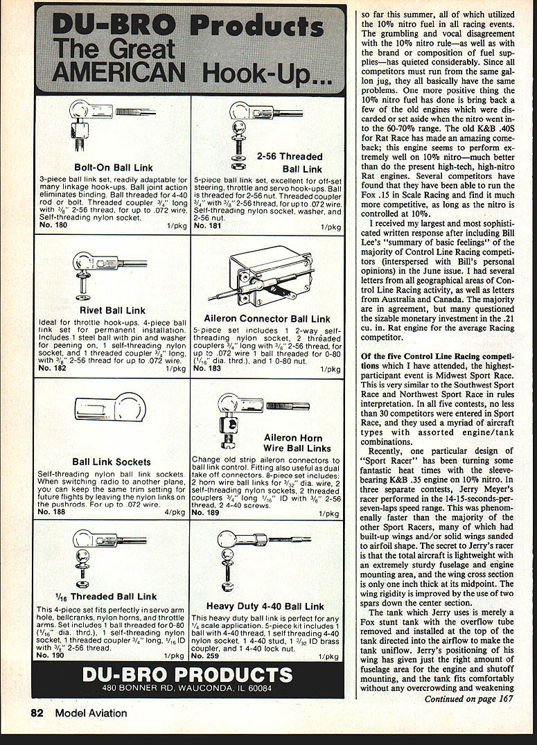
Sport Racer design and performance
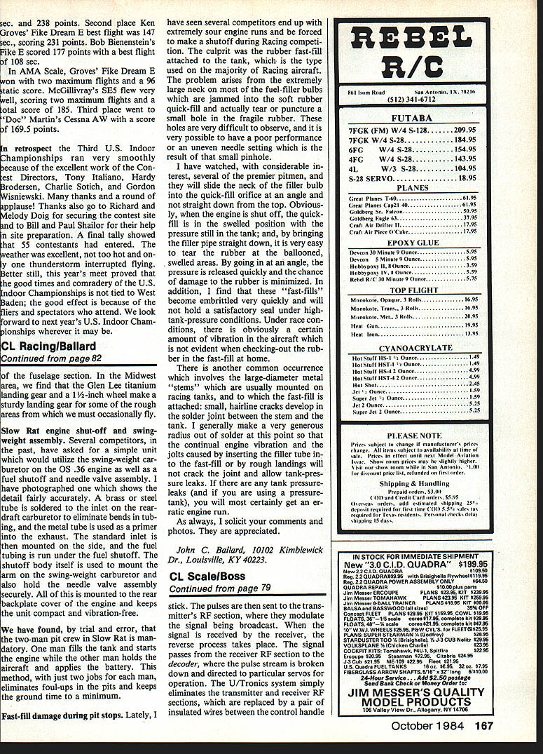
Recently, one particular design of "Sport Racer" has been turning some fantastic heat times with the sleeve-bearing K&B .35 engine on 10% nitro. In three separate contests, Jerry Meyer's racer performed in the 14–15-second-per-seven-laps speed range. This was phenomenally faster than the majority of other Sport Racers, many of which had built-up wings and/or solid wings sanded to airfoil shape.
The secret to Jerry's racer is that the total aircraft is lightweight with an extremely sturdy fuselage and engine mounting area, and the wing cross section is only one inch thick at its midpoint. Wing rigidity is improved by the use of two spars down the center section. The tank Jerry uses is merely a Fox stunt tank with the overflow tube removed and installed at the top of the tank directed into the airflow to make the tank uniflow. Jerry's positioning of his wing has given just the right amount of fuselage area for the engine and shutoff mounting, and the tank fits comfortably without any overcrowding and weakening of the fuselage section.
In the Midwest area, we find that the Glen Lee titanium landing gear and a 1–2 inch wheel make a sturdy landing gear for some of the rough areas from which we most occasionally fly.
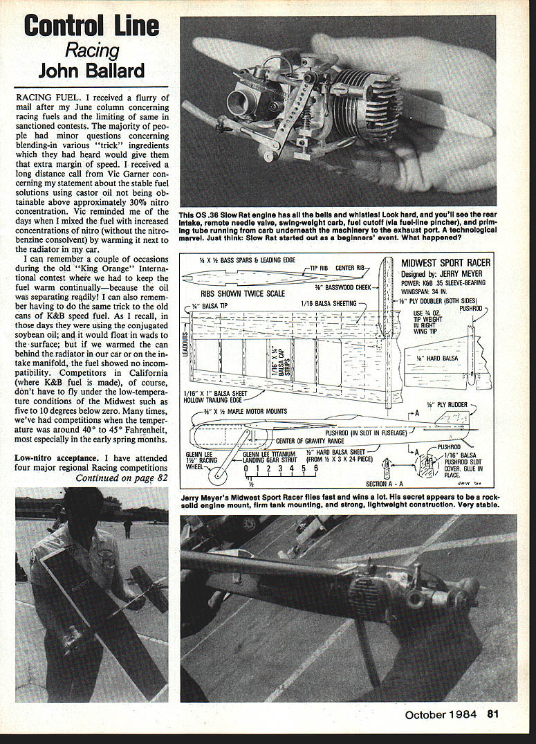
Slow Rat engine shut-off and swing-weight assembly
Several competitors have asked for a simple unit that would utilize the swing-weight carburetor on the OS .35 engine as well as provide a fuel shutoff and needle valve assembly. I have photographed one such assembly that shows the detail fairly accurately.
- A brass or steel tube is soldered to the inlet on the rear-draft carburetor to eliminate bends in tubing, and the metal tube is used as a primer into the exhaust.
- The standard intake is then mounted on the side, and the fuel tubing is run under the fuel shutoff.
- The shutoff body itself is used to mount the arm on the swing-weight carburetor and also to hold the needle valve assembly securely.
- All of this is mounted to the rear backplate cover of the engine and keeps the unit compact and vibration-free.
By trial and error, we have found that a two-man pit crew in Slow Rat is mandatory.
- One man fills the tank and starts the engine.
- The other man holds the aircraft and applies the battery.
This division of tasks, with just two jobs for each man, eliminates foul-ups in the pits and keeps pit time to a minimum.
Fast-fill damage during pit stops
Lately I have seen several competitors end up with extremely sour engine runs and be forced to make a shutoff during racing competition. The culprit was the rubber fast-fill attached to the tank, the type used on the majority of racing aircraft. The problem arises from the extremely large neck on most of the fuel-filler bulbs which are jammed into the soft rubber quick-fill and actually tear or puncture a small hole in the fragile rubber. These holes are very difficult to observe, and it is possible to have poor performance or an uneven needle setting as a result of that small pinhole.
I have watched, with considerable interest, several of the premier pitmen, and they will slide the neck of the filler bulb into the quick-fill orifice at an angle rather than straight down from the top. Obviously, when the engine is shut off, the quick-fill is left in the swelled position with pressure still in the tank; by bringing the filler pipe straight down it is easy to tear the rubber at the ballooned, swelled areas. By going in at an angle, the pressure is released quickly and the chance of damage to the rubber is minimized.
In addition, these fast-fills become embrittled very quickly and will not hold a satisfactory seal under high-tank-pressure conditions. Under race conditions there is a certain amount of vibration in the aircraft not evident when checking the rubber fast-fill at home.
Tank solder joints and pressure leaks
Another common occurrence involves the large-diameter metal stems usually mounted on racing tanks, to which the fast-fill is attached: small hairline cracks develop in the solder joint between the stem and the tank. I generally make a very generous radius out of solder at this point so that continual engine vibration and the jolts caused by inserting the filler tube into the fast-fill or by rough landings will not crack the joint and allow tank-pressure leaks. If there are any tank pressure leaks (and if you are using a pressure tank), you will most certainly get an erratic engine run.
Closing
As always, I solicit your comments and photos. They are appreciated.
John C. Ballard 10102 Kimblewick Dr. Louisville, KY 40223
Transcribed from original scans by AI. Minor OCR errors may remain.

