
Control Line: Racing
John Ballard
10102 Kimblewick Dr. Louisville, KY 40223
Fast-Fill Maintenance and Mounting
I have had several inquiries concerning an improper seal on the KK (Kustom Kraftmanship) black rubber quick-fill fuel tank fitting universally used by almost all Control Line Racing competitors.
- Inspect the slot on arrival. In many cases the slot corners should be eased with a sharp X-Acto blade to allow easy access for the filler bulb tube. Filler bulb tubes commonly measure 3/16" to 1/4" wide; if the slot is not enlarged the quick-fill can be pulled inside out when the bulb is removed.
- Rotate the bulb as it is inserted and removed to minimize friction on the rubber slot.
- Many competitors solder a small ball bearing to the tip of their fuel filler to produce a rounded point, making rapid entrance to the quick-fill much easier.
- For attaching the quick-fill to the brass neck in the tank, I recommend a small automotive fuel-line hose clamp of the spring-tension type (not the screwdriver-tightened type). These keep even pressure on the quick-fill and do not cut into the rubber, avoiding improper seals or holes.
Tank Cleaning
New tank (after fabrication)
- Remove the rear cover and thoroughly wash the interior with a plastic Tuffy-type scrubber or steel wool to remove soldering flux or residual acid.
- Use a detergent, rinse with clear water, then wash the tank with methanol.
- Reattach the rear cover. This minimizes flux or acid remaining in the tank when you add fill tubes, pressure and feed lines, etc.
Used tank (mounted on the aircraft)
- Pour about half a tube of BBs into the tank, add soap and water, and shake the tank back and forth. The rolling action of the BBs cleans residual oil, varnish, and other contamination.
- Dump out the BBs and thoroughly wash the tank with methanol before refueling.
Team Racing
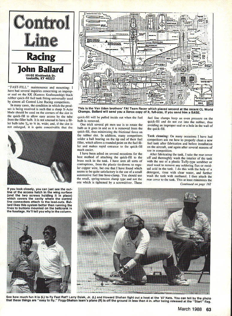
Since acquiring some Russian Team Racer plans, I have received numerous requests from the United States and abroad. I now have a set of plans for the World Finalist second-place aircraft flown by the Dutch Van Uden brothers.
- The plans are drawn on 10 mm squares, so scaling up is straightforward.
- The wording on the plans is in Swedish, but they can be translated into English.
- One specific feature: the airfoil at the elevator area includes about 2 mm of reflex. Several teams build in reflex to avoid the need to fly with continuous up elevator.
These plans were provided by Conrad Cloete of South Africa. If you would like a copy, send a self-addressed, stamped envelope (SASE) and I will forward one.
Internally Connected Flying Wires
Some competitors run flying wires completely through the wing into the fuselage and mount them on buttons attached to the bellcrank. I have found this approach cumbersome because it requires a hatch at the wing-fuselage joint, which can allow fuel contamination and internal deterioration.
My preferred method:
- Attach lead-outs to the bellcrank, then install the buttons on the ends of the lead-outs.
- Construct a rectangular "installation area" near the wing tip, approximately 2 inches inboard from the tip. This simplifies installation and allows a small hatch to be screwed down to contain the wires.
- Place a spacer between the wires to prevent the buttons from touching or catching during rapid elevator movement (such as when tripping the fuel shutoff).
- Use a small hatch cover secured with two 2-56 screws positioned to prevent exhaust residue or refueling liquid from soaking the wood.
- Between rounds, the line storage reel can be wound up and attached to the tip of the wing with a rubber band and a piece of foam rubber; remove the wires when the event is over.
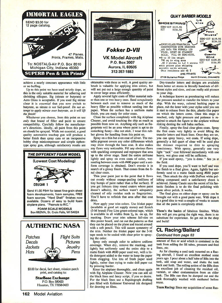
I am enclosing a photo of an internal line connection hatch and some 1987 Nats photos, including one showing the Fogg-Shahan team launching their Rat Racer.
As always, your comments and questions are welcomed.
Transcribed from original scans by AI. Minor OCR errors may remain.

