
Control Line: Racing
John Ballard 10102 Kimblewick Dr. Louisville, KY 40223
PROPER FUEL TANK CONSTRUCTION
On several occasions racing enthusiasts have requested specifications for a foolproof fuel tank construction sequence. Many races and good engines have been lost as the result of a tank leak.
Both Scale and Rat Racers commonly use the standard cylindrical "Rat tank" cut down (Scale — 3 ounces; Rat — 4 ounces). During manufacture the tank is typically soldered with acid-core flux. When you remove the front or rear cover with a torch at medium heat, you will often find minor corrosion and residual flux inside the tank.
Recommended construction/repair sequence:
- Remove all tubes and covers.
- Clean the entire unit thoroughly with Ivory liquid soap and steel wool.
- Rinse with methanol (or equivalent) to remove residue.
- Resolder all joints and tubes using Sta-Brite silver solder with Sta-Brite liquid flux. Sta-Brite’s silver content provides a noncorrosive, ductile bond that tolerates vibration and hard landings.
- After reassembly and before sealing the rear with a freeze-out plug, wash the tank again.
- Install an appropriately sized freeze-out plug for the rear cap — if you have cut down the tank the original rear cover will be too large because the tank tapers. Various sizes of freeze-out plugs are available from auto parts stores. A stout plug also strengthens the rear area of the tank.
- Surround the tank seal with Perm-A-Gasket blue silicone to provide a permanent, fuel-proof, flexible adhesive mounting (useful as a secure mount in a Rat pan or as a vibration damper in profile racers).
If a scratch-built tank is required, be sure each solder seam has an overlapping support flap. If a support flap is omitted, form one on a right-angle mandrel and trim to size. Without the support flap the seam will stress and eventually crack when the tank is full or during a hard landing.
At the conclusion of each racing day spray a small amount of WD-40 into the tank to neutralize the acidic nature of typical racing fuels.
Materials and tips
- Sta-Brite silver solder and Sta-Brite liquid flux
- Ivory liquid soap and steel wool for initial cleaning
- Methanol for final wash
- Perm-A-Gasket blue silicone for sealing and vibration damping
- Freeze-out plugs (various sizes from auto parts stores)
- WD-40 for neutralizing tank interior after racing
FLYING WIRE CONSTRUCTION
I have observed several control-line failures during racing heats. Careful inspection showed these failures commonly resulted from three minor construction variations that deviate from the AMA rule book.
Common problems:
- Wrapping wire size — Using standard spool copper wire that is too thick can bind or hang up in internal line attachments. Use fine copper wrapping wire specified for line ends.
- Number of loops — The AMA rule book specifies two loops of wire around the spindle for .018 (and .015) flying wires. Some builders use only one loop; this is weaker and more failure-prone.
- Wrap placement — Failing to wrap the wire close enough up to the spindle allows flexing at the end of the wrap and eventual breakage.
Strict adherence to the AMA diagrams and instructions will minimize aircraft and engine damage and reduce the danger to competitors and spectators.
FLYING TECHNIQUES
A recent meet at Whittier Narrows, CA drew many entrants for Control Line Racing events, including Mouse I and II, Scale Racing, Slow Rat, Fast Rat, and Team Race.
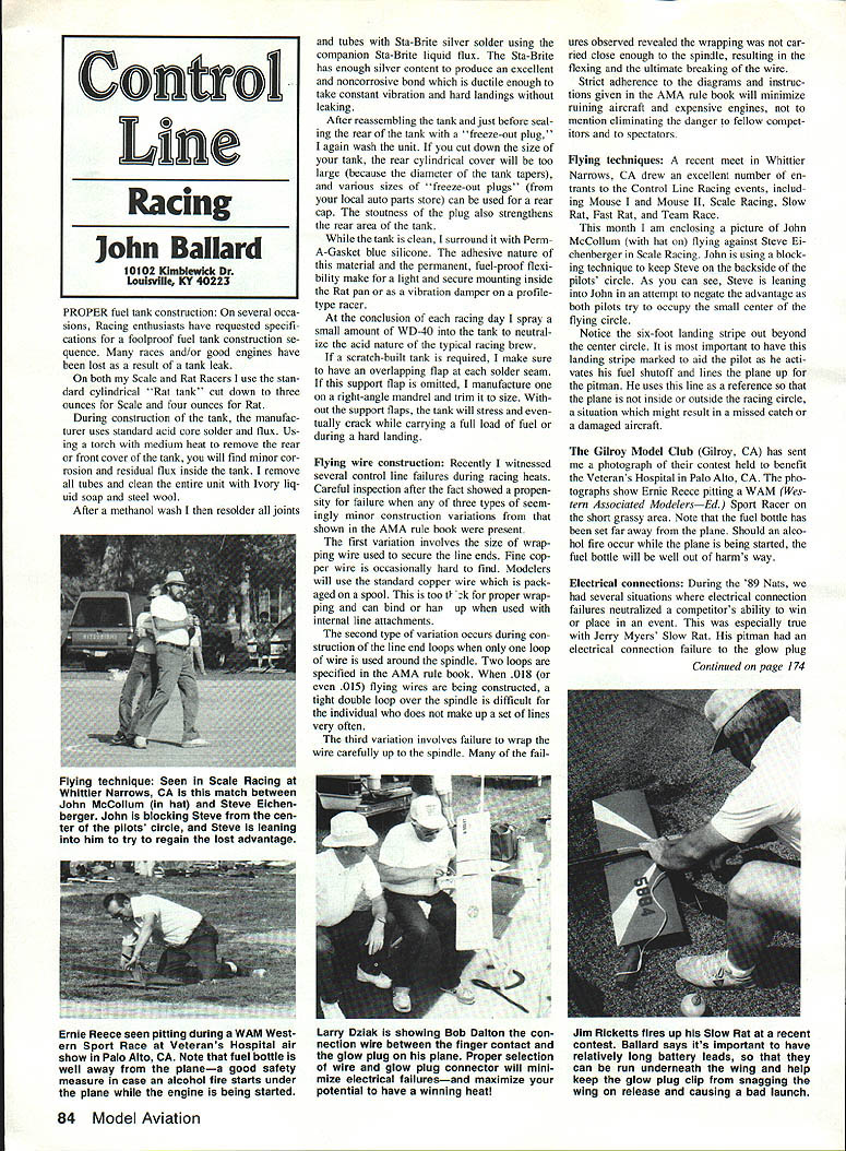
Blocking technique: In Scale Racing John McCollum (with hat) was photographed flying against Steve Eichenberger. John used a blocking technique to keep Steve on the backside of the pilots' circle; both pilots attempted to occupy the small center of the flying circle and Steve leaned into John to negate the advantage.
Landing stripe: Note the six-foot landing stripe beyond the center circle. Marking a landing stripe is important to aid the pilot when activating the fuel shutoff. If the pitman uses the line as a reference and the plane is inside or outside the racing circle incorrectly, a missed catch or damaged aircraft can result.
Safety practice: The Gilroy Model Club (Gilroy, CA) sent photos of a contest benefiting the Veteran’s Hospital in Palo Alto, CA. Photos show Ernie Reece pitting WAM Ed’s Sport Racer on a short grassy area with the fuel bottle set well away from the plane. If an alcohol fire occurs while starting the plane, the fuel bottle will be out of harm’s way.
ELECTRICAL CONNECTIONS
At the 1989 Nats several competitors were neutralized by electrical connection failures. One notable elimination was Jerry Myers’ Slow Rat: a pitman’s electrical connection failure at the glow plug removed a top contender from competition.
Causes and recommendations:
- Failures usually originate in the wire to the glow plug. Profile-style racers produce significant vibration that can fatigue and crack wiring or loosen connections at the plug.
- Use vinyl-coated stranded copper wire (not solid wire). Prefer strands with at least 20 filaments and a vinyl coating about 1/32" thick. Stranded wire resists vibration-fatigue far better than solid wire.
- Avoid makeshift glow-plug clips fashioned from .031 music wire. These spring clips can break the wire or the solder joint and are difficult to remove once glued.
- Prefer a small brass alligator clip for the glow-plug connection. Although slightly bulky, the spring action reduces stress on the solder and is easy to remove when changing plugs.
- To reduce failure at the solder joint of the wire to the alligator clip, slide a short length of small-diameter silicone tubing over the clip area to absorb vibration (tip from Larry Dziak).
- The opposite end of the lead should be soldered to a solid finger contact on the plane, and the battery lead must be attached in a positive, secure manner.
Control Line: Racing — John Ballard, 10102 Kimblewick Dr., Louisville, KY 40223
Transcribed from original scans by AI. Minor OCR errors may remain.

